Introduction
Additive manufacturing or 3D printing, is a process of creating the desired objects or parts by building them layer by layer from a digital model.
Using additive manufacturing principles, this project aims to design a 3D printed enclosure for the electronics parts, composed of a single stepper motor and controller, of a given conveyor system (see figure below).
From our understanding of manufacturing processes and 3D modeling that we learned in this course, we are utilizing Fusion 360, a computer-aided design (CAD) software, to create the 3D design model.
As part of the process, we will use slicing software (Bambu Studio) to slice the digital model into thin layers and generate the G-code file. This G-code contains instructions for the 3D printer, specifying how each layer should be printed, including details like the path of the print head, the amount of material to be extruded, and the temperature settings.

By the end of it, we should not only be able to design and print parts but also have gained an understanding of rapid prototyping, ideation, iteration, etc., and how to safely operate a 3D printer.
Design Goals
We are expected to design and print an enclosure model that:
- Allows the electronic components to fit.
- Avoids overhangs that require massive support.
- Implements a strategic/better print orientation.
- Leaves appropriate clearances and room for connectors and wires.
- Is usable, and where users can view the screen and access the buttons.
- Has parts that are easy to assemble and disassemble.
It’s also important to remember the principles of Design for Manufacturability (DFM). In this case, we need to understand the manufacturing processes available before designing the part. In addition, it is better to just start with simpler designs that satisfy the given criteria rather than complex designs that are challenging to print.
Phase 1. Gathering Information and Brainstorming

In this phase, I implemented two ways to get the information I needed.
- Used the caliper and measured all critical dimensions of the electronic components/parts.
- Utilized the internet and obtained the accurate information or dimensions of the given parts.
NEMA 17 Stepper motor
ZK-SMC02 driver
From the pieces of information, combined with all the measurements I obtained, I can now create a rough guide and quick/simple sketches of desired features.
I also downloaded the exact 3D model of the stepper motor from GrabCAD.com and imported it into the Fusion 360 workspace. I made it my reference to easily create sketches and set reasonable dimensions and tolerances. From there, I used the extrude feature and other tools to develop and complete the model.
Phase 2. Rapid Prototyping
From the initial sketches, I first created the CAD model and printed the part that mounts the stepper motor driver. This phase enables the efficient creation and testing of models or features because the physical prototype can be tested for fit, function, and design.
Rapid prototyping is also excellent for catching design errors early in the development process. If an error is found, you can easily modify the digital model and print a new prototype, refining the design step by step. This is what I did which also allowed me to do some quick iterations on the spot along the way.
Phase 3. Final Iteration
Although this cycle can be repeated multiple times until the design is perfected, I also need to consider practical limitations and try to save resources.
In this case, in my opinion, the prototype passes all requirements (e.g., fit, function, usability, structural integrity), and is ready for the next stage. Further iterations will result in only minor improvements that don’t significantly impact the overall design.
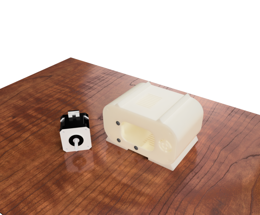
Based on the feedback from the prototyping phase, I then made major adjustments and finalized the 3D design model, as shown in the figure below.

Final Design Print
After countless hours of iterating my model, I was finally able to create and print the desired part.
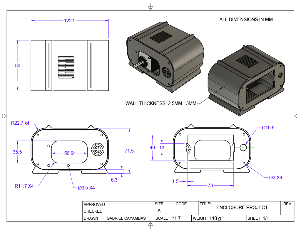
- Overall dimension: Length = 122.5 mm, Width = 80 mm, height = 71.5 mm
- Weight: 110 g
- Wall Thickness: 2.5 mm – 3 mm
- Material: PLA Plastic
The print consists of two parts: the main enclosure body and the back panel, joined together using screws. Screw mounting holes are also added on the front panel to secure the steeper motor inside. For, ventilation, I added rectangular holes (grills) on the top and bottom of the enclosure (see figure below).

My initial design was to separate the front and back panels from the main body. However, this creates an overhang that requires support in its best print orientation; therefore, I decided to join the front panel with the main body instead.
All the components, including the wires fit inside. I also designed this part to have a strategic/better print orientation, avoiding overhangs. I printed it without enabling support.
Design Drawing

Parts Assembly

| PARTS LISTS | ||
| PART NO. | QTY | DESCRIPTION |
| 1 | 7 | SCREWS |
| 2 | 1 | NEMA 17 MODEL |
| 3 | 1 | MAIN ENCLOSURE BODY |
| 4 | 1 | BACK PANEL |
Conclusion
In the end, this hands-on project not only improved my understanding of additive manufacturing but also enabled me to solve challenging problems. Although there are some areas of improvement, I’m still satisfied with the result. Through this experience, I gained a deeper understanding of the entire 3D printing workflow, from conceptual design to the finishing touches.
Creator and Editor at AnitoCircuits.com based in Toronto
