A schematic diagram is a simplified representation of various circuit elements. It uses lines and standard graphic symbols to depict the interconnection of components and other parameters.
Nowadays, software like Fritzing and Tinkercad uses realistic pictures to represent different components and connections. However, please note that schematic diagrams also focus on the functional relationships within a circuit. For example, a diagram not only displays how components are connected but also illustrates how electricity flows through a branch circuit or helps you analyze networks.
Now, if you’re starting to learn electronics, we recommend that you give enough time to learn how to read and interpret a circuit diagram.
Why Learn to Read Circuit Diagrams?
- Clarity and Simplicity: Schematic diagrams provide a clear and concise way to visualize and understand the structure and operation of electrical circuits, especially complex ones.
- Standardization: The use of standard symbols ensures that anyone familiar with electronics can interpret a schematic diagram, regardless of the specific components used. In other words, they provide a common language for anyone working with electrical or electronic circuits.
- Circuit Analysis: Schematic diagrams are essential for analyzing circuit behavior, and calculating current flow, voltage drops, and other electrical parameters.
- Troubleshooting: For us technicians, they serve as a roadmap to identify and repair faults in electrical circuits.
Identify Key Components and Symbols
To read a diagram effectively, it’s important to recognize the different symbols and functions of electronic components and electrical systems.
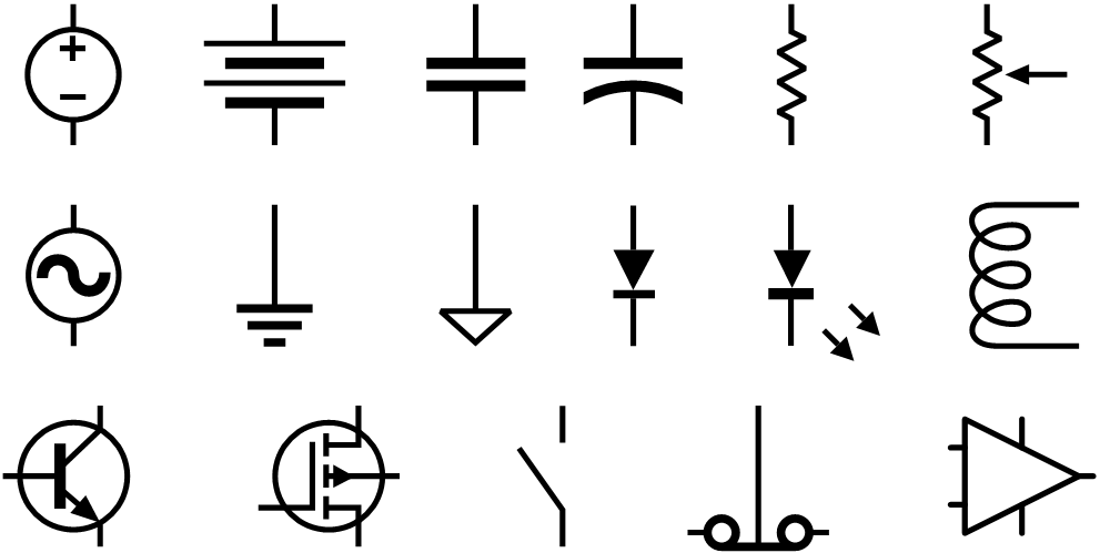
In most circuits, you will always encounter schematic symbols for common components like resistors, capacitors, inductors, transistors, diodes, switches, some ICs, and sources (e.g., batteries).
If you still don’t have any idea about these components and symbols, you can always refer to these guides:
- Explore the schematic symbols of common electronic components.
- Learn more about the basic electronic components in circuits.
Identify the Power Sources
The next step is to identify the power source. As previously mentioned, this could be a DC battery or an AC power supply. When working with a DC source, ensure you pay attention to the polarity (positive and negative terminals). Typically, you’ll see a battery symbol or a power supply symbol with clearly marked terminals.
However, please note that in DC circuits, the supply voltage can be represented by various symbols, such as a simple “+” sign, an arrow pointing upward, or even a “VCC” label, depending on the diagram’s conventions.

Additionally, these symbols aren’t directly paired with a ground symbol because they represent a more generalized or abstract view of the circuit’s positive supply, particularly in cases where the ground is implicit or assumed. This helps simplify the schematic.
Recognize Where Current Flows
The current flow helps you break the circuit diagram down into functional sections. For instance, if you need to examine a power supply schematic, you can follow the flow of current through a rectifier, filter, and regulator.
The current direction also shows how components interact with one another. In most diagrams and analyses, they use conventional current flow (positive to negative).
See Also
- Explore the Difference Between Alternating Current (AC) and Direct Current (DC).
Trace the Connections
Each line in the diagram represents a wire. The lines show how connections are made and show the paths for current to flow. Some schematics often refer to these connections as “nets.”
To properly analyze the diagram, follow the lines starting from the load to each component to the power supply. However, it’s important to note how components are connected, if they are in series (one after another) or in parallel (side by side).
To analyze series and parallel connections, you need to understand the basic principles that govern their behavior. Components are considered connected in series if the same current flows through them. On the other hand, they are connected in parallel if they share the same voltage across their terminals.
Recommended Reading
- Explore Resistors in Series and Parallel.
- Learn more about Capacitors in Series and Parallel.
Locate Connection Points (Nodes)
If you still don’t understand series and parallel connections, then better start recognizing what a node is in a circuit diagram.
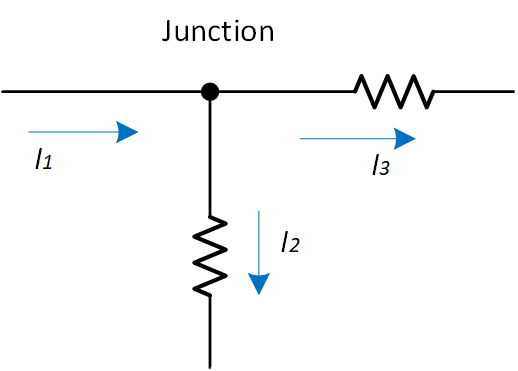
A node is a point on a circuit where two or more components are connected. They are typically shown in a diagram as dots where the lines intersect, indicating that all the components connected to that node share the same electrical potential or voltage.
In other words, a node is a junction where current can split or merge.
Junctions
When a wire splits into two directions, it creates a junction, which is represented on the schematic by a node.
No Connection
The absence of a node at a junction indicates that the wires are simply crossing each other without being connected.
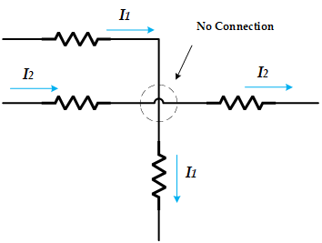
However, in some schematic diagrams, even without a node, the lines may actually be connected. This can be tricky, so you need to be cautious when analyzing these junctions to avoid misinterpreting the connections.
Always double-check the diagram’s conventions and look for subtle cues that might indicate a connection. For example, if a junction is marked with a dot, it’s safe to assume that lines without a dot at their intersection are simply crossing without a connection (see figure below).
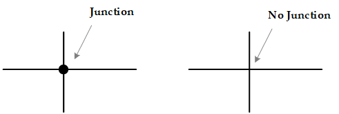
On the other hand, if the junction isn’t marked with a dot, you can expect the lines to cross without connection, often represented by one line curving over the other, as shown in the figure below.

Note Component Placement
Recognizing every symbol isn’t enough. You also have to learn each component’s function and operation. Each component influences the circuit’s behavior, and you can easily identify what the diagram or different sections are designed to do.
For example, if you see a capacitor placed near a power supply, it likely serves to smooth out voltage fluctuations. If the capacitor is connected in series with a resistor, the circuit could form an RC (resistor-capacitor) filter.
Let’s take a look at the diagram below (a simple LED circuit). If I’m going to interpret it, the capacitor connected in parallel with the load functions as a decoupling capacitor, helping to stabilize the voltage by filtering out noise. The resistor in series acts as a current limiter, protecting the LED from excessive current.
It’s also important to note that polarity matters. Components like LEDs and electrolytic capacitors have specific positive and negative terminals. So you know that a diagram makes sense if they are connected properly in a circuit.
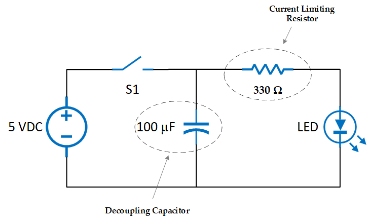
It’s also the foundation of diagnosing problems in electronics. Knowing what each component does helps you spot issues. For example, if an LED in your project fails to light up and the schematic indicates that it is connected to a resistor, knowing that a resistor restricts current can prompt you to verify if the resistor value is too high.
Once you’re familiar with these concepts, it’s much easier for you to recognize and understand a circuit diagram.
Recommended Reading
- Explore what RC Time Constant is.
- Learn more about Capacitors.
- What is a Bipolar Junction Transistor (BJT)?
Breakdown Schematic into Functional Blocks
In complex schematics, you can break down the circuit diagram into functional blocks by recognizing groups of components that work together. For example, you might recognize an amplifier stage, filter stage, or power regulation stage in certain circuits.
Let’s examine the regulated power supply circuit below. The circuit is divided into four main stages: the transformer, rectification, filtering, and voltage regulation. The AC input first passes through the transformer, then undergoes rectification and filtering, before the voltage is regulated. By the end of this process, the AC signal is converted into a stable DC output.
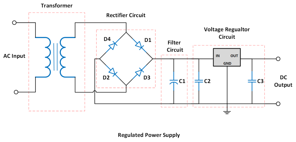
By breaking down the circuit diagram into sections, it’s much easier to visualize and understand each component’s role within these stages. This also helps clarify how the entire circuit operates.
Identify Signal Paths
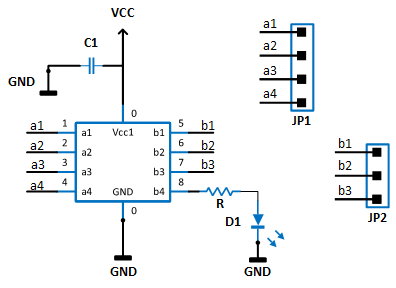
Moreover, in more advanced circuits, there may be input and output signals. Input signals might come from sensors, switches, or other devices, triggering the circuit’s response. Output signals may activate devices like LEDs, motors, or buzzers.
You may encounter labels such as IN, OUT, VCC, GND, VIN, or specific pin numbers for microcontrollers or ICs in certain schematic diagrams. These labels indicate where signals are input or output.
Practical Tips for Reading Circuit Diagrams
Look for the Labels
Along with diagrams, reference designators are included to help organize the schematic and make it more readable, particularly for complex circuits with many components. You often see these labels for each component (e.g., R1 for the first resistor).
We also recommend exploring circuit diagrams that come with detailed documentation, such as projects from electrical or electronics engineering students. These resources often provide insight into component selection and design rationale. If you’re unfamiliar with certain symbols, you can always refer to the Bill of Materials (BOM) (if included), which lists each component and its specifications. This can be especially helpful in identifying parts and understanding how they fit into the overall circuit design.
Look for Common Patterns
Many circuits reuse common patterns like voltage dividers, amplifier stages, and filter networks. Recognizing these can speed up your understanding of a diagram.
Practice, Practice, Practice
Start by building simple circuits on a breadboard, following their schematic diagrams. We recommend starting with an LED circuit, which usually involves a battery, switch, LED, and connecting wires. Once you feel confident in your knowledge and skills, you can move on to more complex projects.
From experience, the more you work with schematic diagrams physically, the more comfortable you’ll become in interpreting and analyzing them. With consistent practice, reading circuit diagrams will eventually become second nature.
Also, look for practice problems in textbooks or online resources (or from this website) and try to apply the different circuit analysis techniques you’ve learned.
What’s Next?
Please ensure that you also understand concepts like current, voltage, resistance, power, Ohm’s Law, Kirchhoff’s Laws (voltage and current), series and parallel circuits, etc.
It’s pretty easy to read a circuit diagram. However, this is just one of the first steps in learning electronics. Simply being able to read the symbols and connections in a circuit diagram doesn’t mean you fully understand how it works. You won’t be able to understand how circuits work or analyze them, without a solid grasp of these fundamentals.
Next Steps
- Learn more about Current, Voltage, and Resistance
- Explore What is Ground in Electronic Circuits
Creator and Editor at AnitoCircuits.com based in Toronto
