A Zener diode is a special type of semiconductor diode designed to allow current to flow not only in the forward direction but also in reverse under specific conditions. What makes it unique is that it is heavily doped to function in the reverse breakdown region.
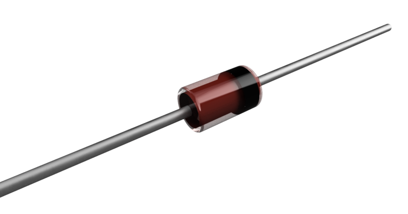
When a Zener diode is forward-biased, it operates like a standard diode. However, in reverse bias, its behavior changes a little bit. Once the reverse voltage exceeds a certain threshold, known as the Zener breakdown voltage, the diode starts to conduct in reverse.
This characteristic enables it to maintain a stable voltage across its terminals, making it well-suited for voltage regulation. Read more to find out!
Zener Diode Symbol
The symbol for a diode consists of a triangle pointing toward a vertical line. The triangle represents the direction of current flow in forward bias (from anode to cathode), while the vertical line represents the cathode, where current exits.
For a Zener diode, the same basic symbol is used, but with bent lines at the tip of the vertical bar. According to some textbooks, this indicates its ability to allow current to flow in both directions.
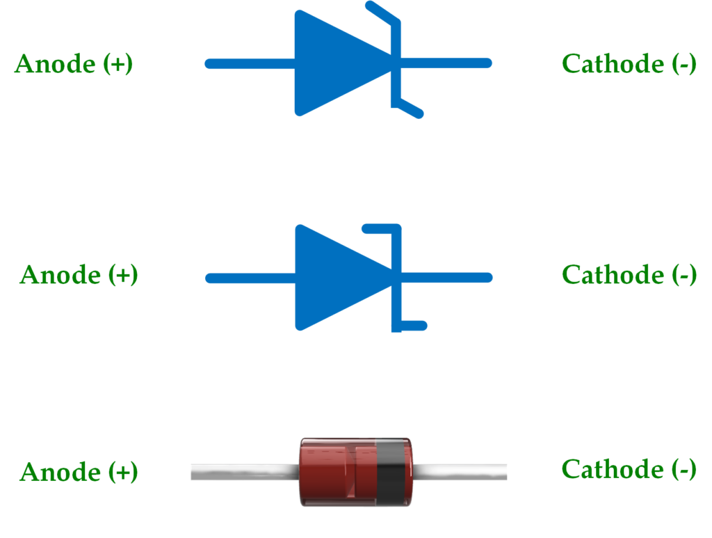
Some symbols for Zener diodes depict horizontal lines rather than diagonal ones at the cathode side. Both variations can be found in different circuit diagrams, but the horizontal lines are also a common representation.
Zener Breakdown vs. Avalanche Breakdown
Zener diodes are designed to operate in reverse breakdown, and there are two breakdown mechanisms.
- Zener breakdown
- Avalanche breakdown.
Zener breakdown
This breakdown happens when a Zener diode, in reverse bias, experiences a voltage high enough to cause the electric field across its junction to become strong enough to pull electrons from their atomic bonds. In a typical Zener diode, this occurs at lower voltages, usually below 5.5 volts.
Moreover, this process allows current to flow in reverse, while the diode keeps the voltage stable at a specific value called the “Zener breakdown voltage” (Vz).
Avalanche breakdown
It occurs at higher voltages, typically above 5.5V. In this process, free electrons in the depletion region are accelerated by the electric field, gaining enough energy to knock other electrons loose when they collide with atoms. These newly freed electrons continue to collide, creating a chain reaction (like an avalanche) that rapidly increases the current flowing through the diode.
Now, a Zener diode can experience both Zener and avalanche breakdown, but one mechanism will dominate depending on the voltage. As described earlier, the Zener effect is dominant at voltages below 5.6 volts, while the avalanche effect takes over at voltages above that.
It’s also important to note that while regular diodes can be damaged by avalanche breakdown, Zener diodes are specifically designed to withstand it. This ability to safely handle the sudden surge in current also makes Zener diodes essential for applications like overvoltage protection.
Recommended Reading
- Learn more about Bipolar Junction Transistors (BJTs).
V-I Characteristic Curve
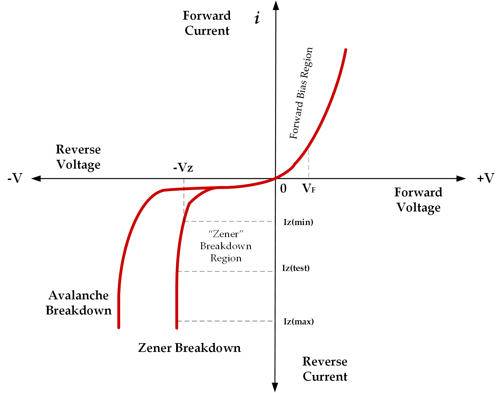
The V-I (Voltage-Current) characteristic curve visually shows the relationship between the voltage across a diode and the current flowing through it. This curve helps understand how the diode behaves under various operating conditions, such as forward bias, reverse bias, and breakdown regions.
Forward Bias Region
In the forward bias region, the Zener diode behaves like a regular diode. As the forward voltage increases, the current increases exponentially.
The graph also shows a steep rise in current with a small increase in voltage in this region.
Reverse Bias Region
The behavior of the Zener diode in the reverse bias region sets it apart from a regular diode. At low reverse voltages, only a small leakage current flows.
However, as the reverse voltage increases and reaches the Zener breakdown voltage (Vz), the diode begins to conduct significant current while maintaining a stable voltage across it.
Breakdown Region
At this stage, the electric field in the depletion region becomes strong enough to break the covalent bonds that hold electrons in place. This causes a sudden rise in reverse current, allowing a large current to flow through the diode.
On the characteristic graph, this is shown by a nearly vertical line, meaning the voltage stays almost constant even as the current increases sharply.
Applications in Circuits
Voltage Regulation
One of the most common uses of a Zener diode is in voltage regulation. They are used to create simple shunt regulators that maintain a constant voltage across a load, regardless of fluctuations in the input voltage or load current
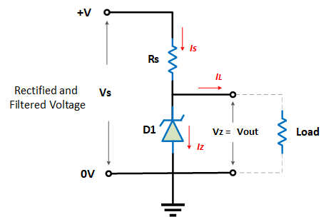
In this configuration, the Zener diode is connected in parallel with the load, and a series resistor (Rs) is placed between the power supply and the circuit to limit current. When the voltage across the Zener diode exceeds its breakdown voltage (Vz), the diode begins to conduct, maintaining a constant voltage across the load. Any excess voltage from the power supply is dropped across the series resistor. This prevents the Zener diode from overheating.
Overvoltage protection
Zener diodes can also be used for overvoltage protection, protecting sensitive components from voltage spikes by shunting excess voltage to the ground.
Clipping Circuits
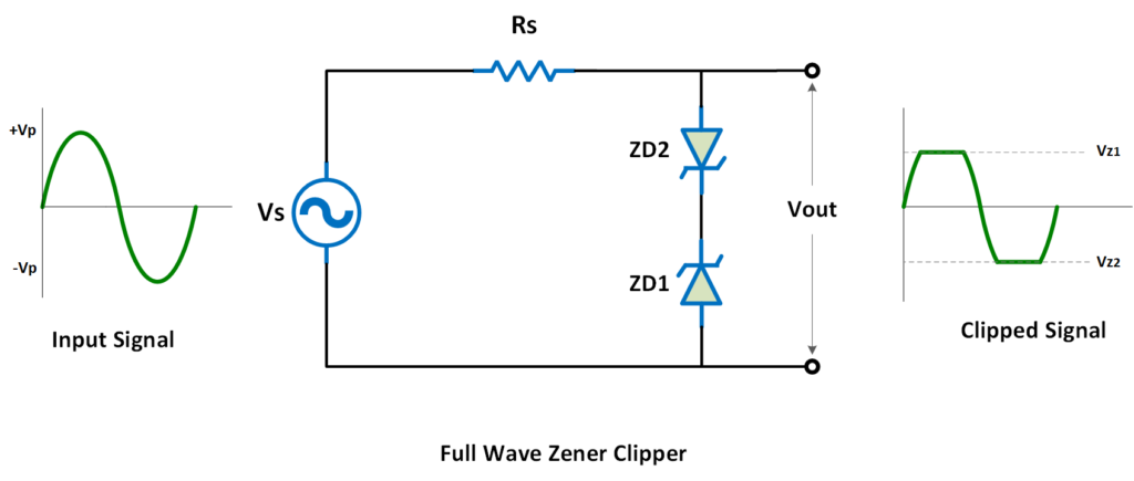
Zener diodes can also be used in clipping circuits to limit the voltage swings in signal processing applications. For instance, in audio circuits, they prevent distortion by clipping the input signal at specific voltages.
Testing
When testing a Zener diode with a multimeter in diode mode, you’re essentially checking it like a regular diode, focusing on its forward bias.
In forward bias, it should show a typical diode forward voltage drop (around 0.7V for silicon diodes). However, in reverse bias, the multimeter will likely show an open circuit because the reverse voltage applied by the multimeter is much lower than the Zener breakdown voltage.
To confirm its voltage regulation properties, you’ll need to set up a test circuit that applies a reverse voltage greater than the Zener voltage. Once this reverse voltage exceeds the breakdown voltage, the Zener diode will conduct, and you can observe the stable voltage it maintains.
Next Step
- Learn How to Measure Voltage, Current, and Resistance.
- Explore the Basic Electronic Components in Circuits.
Creator and Editor at AnitoCircuits.com based in Toronto
