To work with electronics, the first step is learning how to manage current flow. Resistors are key for this—they’re the simplest tool for controlling it. This lesson will explain what resistors do, how to interpret their color bands, and why they’re a must-have for most circuits.
What is a Resistor?
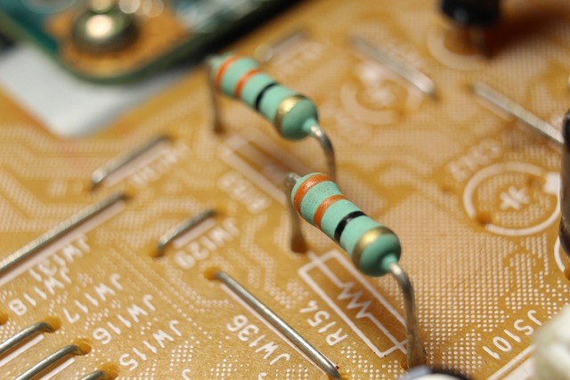
A resistor is a passive two-terminal component that resists the flow of electric current. Think of it like a narrow pipe in a plumbing system — it restricts how much water (or in our case, current) can pass through.
Purpose of a resistor:
- To limit current in a circuit
- To divide voltage between components
- To protect sensitive devices like LEDs
- To bias transistors or stabilize signals
You’ll find resistors in nearly every circuit, from the simplest LED flasher to complex microcontroller-based systems.
See also
- Learn more about Potentiometers and Variable Resistors.
Understanding Ohm’s Law (V = IR)
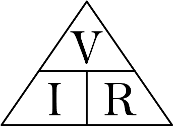
To understand how resistors work in a circuit, we need to revisit Ohm’s Law:
\[ V = I × R \]
- V = Voltage in volts (V)
- I = Current in amperes (A)
- R = Resistance in ohms (Ω)
This law tells us how voltage, current, and resistance relate. If you know two of the values, you can always find the third. Let me show you with an example:
Example: Let’s say we have a 9V battery and want to power an LED that operates safely at 20mA (0.02A).
Using Ohm’s Law:
\(R = V / I\)
R = 9V / 0.02A = 450 Ω
So, we need at least a 450-ohm resistor in series with the LED to prevent it from burning out.
Recommended reading
- Explore Resistors in Series and Parallel.
- Learn more about Capacitors in Series and Parallel.
Reading Resistor Color Codes
Resistors come in different shapes and sizes. But here’s the tricky part: most resistors are so small that printing numbers directly on them is impractical.
So, how do we know their resistance value?
That’s where color bands come in — a clever, compact system to encode resistor values using color stripes.
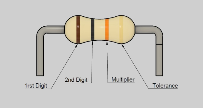
Most through-hole resistors use a 4-band or 5-band color code. These colored bands represent numbers, multipliers, and tolerances. Here’s how to read them:
Band 1: First digit
Band 2: Second digit
Band 3: Multiplier (how many zeros to add)
Band 4: Tolerance (accuracy of the resistor)
Here’s the standard color-to-number chart used in resistor codes:

Example: Red, Black, Orange, Gold

- Red = 2
- Black = 0
- Orange = ×1000
- Gold = ±5%
Value: 20 × 1000 = 20,000 ohms or 20kΩ ±5%
ⓘ Note
Orientation matters: The tolerance band (often gold or silver) is usually spaced farther apart or positioned last. Start reading from the opposite side.
Use a calculator or chart if you’re just starting out. There are many online tools that let you input colors to get resistance.
Why Tolerance Matters?
Resistors aren’t always exact. The tolerance tells you how much the actual resistance may vary from the printed value.
For example:
- A 100Ω ±5% resistor might measure anywhere between 95Ω and 105Ω.
- For high-precision circuits (e.g., oscillators, sensor interfaces), you’ll want resistors with tighter tolerances like ±1% or ±0.1%.
What’s Next?
Use a Multimeter to Measure Resistance. Even if you know how to read color codes, it’s always a good idea to double-check your resistor with a multimeter.
Steps:
- Set your multimeter to resistance mode (Ω).
- Place the probes on either side of the resistor.
- Read the value displayed. It should be close to the labeled value (within the tolerance range).
⚠ Caution
Always measure resistors out of the circuit for best accuracy, as other components might affect the reading.
Next Steps
- Learn How to Measure Voltage, Current, and Resistance in a Circuit.
- Explore the Basic Electronic Components in Circuits.
Creator and Editor at AnitoCircuits.com based in Toronto