Have you ever wondered how to measure the rate at which a signal changes? That’s exactly what a differentiator does. Using an op-amp, this clever circuit turns rapid voltage changes into sharp spikes.
Whether it’s sharpening signals, detecting edges, or solving calculus problems in hardware, the differentiator is a powerful and often overlooked tool in electronics.
What Is Differentiation?
Before diving into circuits, let’s start with the basic idea: Differentiation in mathematics measures how quickly something changes.
In electronics, differentiation is the process of measuring how fast a voltage signal changes over time.
Think about a square wave, a signal that suddenly jumps from low to high. A differentiator circuit produces spikes whenever the signal suddenly jumps, highlighting the “moments of change.”
Ideal Differentiator Op-Amp Configuration
The ideal differentiator uses a simple configuration:
- A capacitor
Cis placed at the input. - A resistor
Rfis placed in the feedback loop.
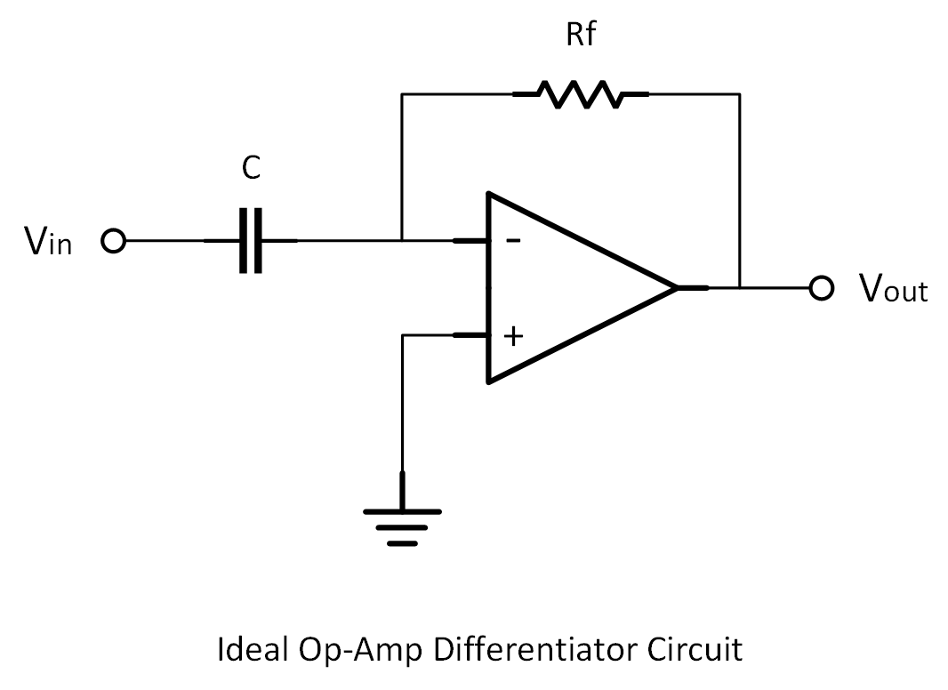
The key equation governing the output voltage is:
This means the output is proportional to the rate of change of the input signal.
- If the input rises quickly, the output will be a large negative spike.
- If the input falls quickly, the output will be a large positive spike.
Many electronics hobbyists use general-purpose op-amps like the TL081 or LM741 to experiment with ideal differentiator circuits, though more modern options like Texas Instruments’ OPA2134 offer better noise performance.
Moving on, let’s take a look at how a differentiator reacts to different input signals based on how quickly the voltage changes.
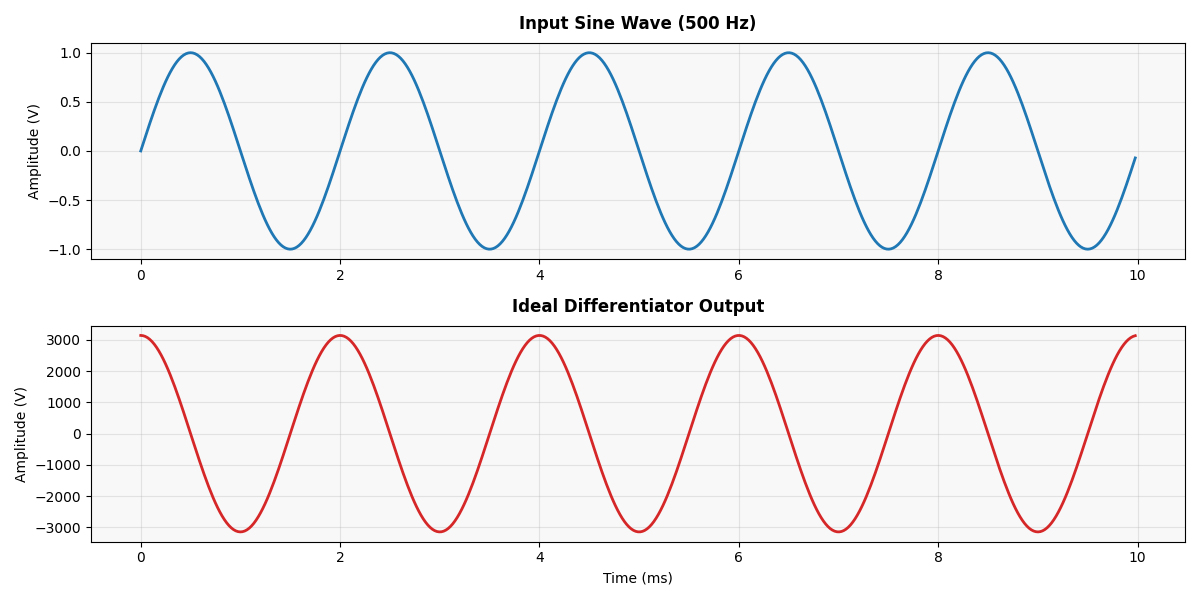
Sine Wave Input → Cosine Wave Output
When a 500 Hz sine wave is fed into the differentiator, the output should theoretically be a 500 Hz cosine wave—a differentiated version of the input, phase-shifted by 90° and scaled by the circuit’s gain.
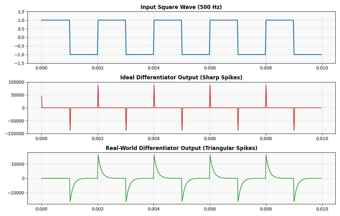
Square Wave Input → Spikes at Transitions
Now, feeding a square wave into the differentiator produces narrow, sharp spikes at the edges. A rising edge produces a negative spike, and a falling edge produces a positive one.
Why? Because the derivative of a sudden step (instantaneous voltage change) is a very large spike. The differentiator “reacts” only at the edges where the signal changes.
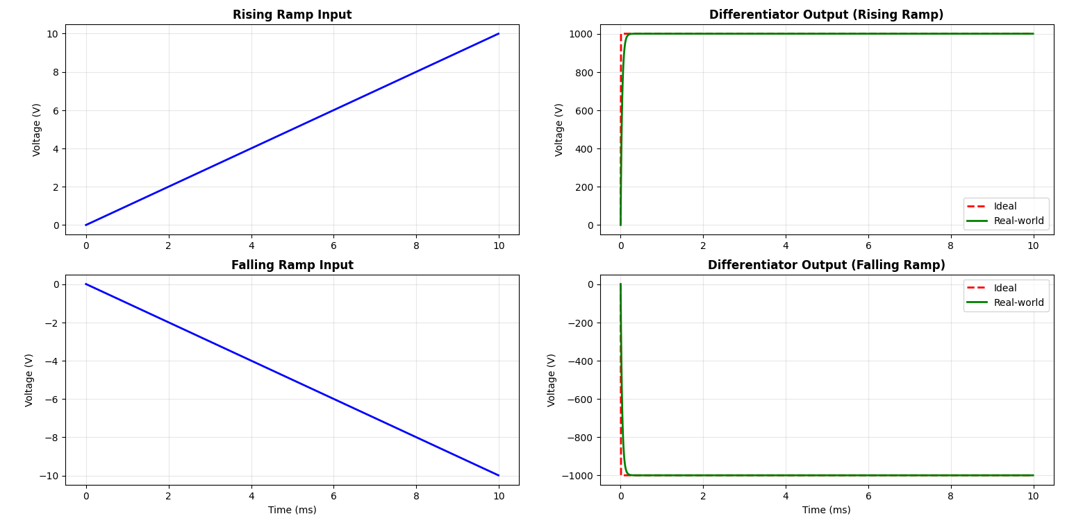
Ramp Input → Constant Output
A ramp signal rises at a steady, constant rate (like a straight diagonal line). Since the slope is constant, we expect the differentiator to output a constant voltage.
Positive constant if ramp is rising and negative constant if ramp is falling. In simple words, you should see a flat, steady output that matches the slope of the ramp.
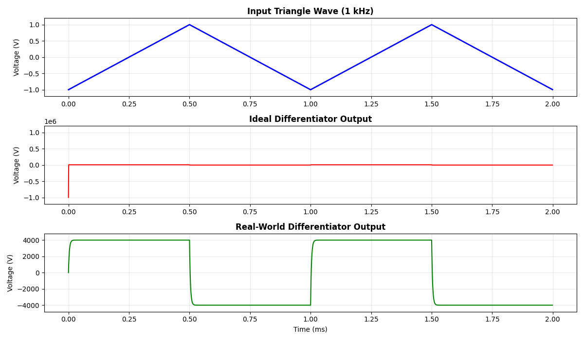
Triangle Wave Input → Square Wave Output
A triangle wave rises and falls linearly, meaning constant positive and negative slopes. We expect the differentiator to output a constant positive voltage when the input is rising, and a constant negative voltage when the input is falling, or in other words, a square wave output.
ⓘ Note
For simulation and testing, tools like LTspice or Multisim can help you visualize these waveform relationships without breadboarding.
Applications of Differentiator Circuits
Differentiators are found across many industries and systems:
| Application | Purpose of Differentiator |
| Edge Detectors | Detect rising/falling edges |
| Pulse Shaping | Restore sharpness in pulses |
| High-Pass Filtering | Remove slow trends, pass fast changes |
| Motion/Acceleration Detection | Find velocity or acceleration |
| Analog Computers | Solve differential equations |
| Seismic/Vibration Monitoring | Detect sudden shifts |
| Oscillator Circuits | Generate complex waveforms |
| Noise/Spike Detection | Identify signal anomalies |
Recommended readings
- Explore Signal Analysis: Understanding Frequency, Amplitude, and Phase.
- The Basics of Analog-to-Digital Conversion (ADC).
Real-World Challenges of Building Differentiators
While the theoretical concept is simple, real differentiator circuits come with some hurdles. Let’s unpack them.
1. Noise Sensitivity
Mathematically, a differentiator boosts high frequencies, and noise is often high frequency. That means a pure differentiator can turn tiny noise into huge output spikes.
2. Practical Differentiator Design
To prevent noise overload, we make two key changes:
- Add a series resistor
R1at the input - Place a small capacitor
Cfacross the feedback resistor
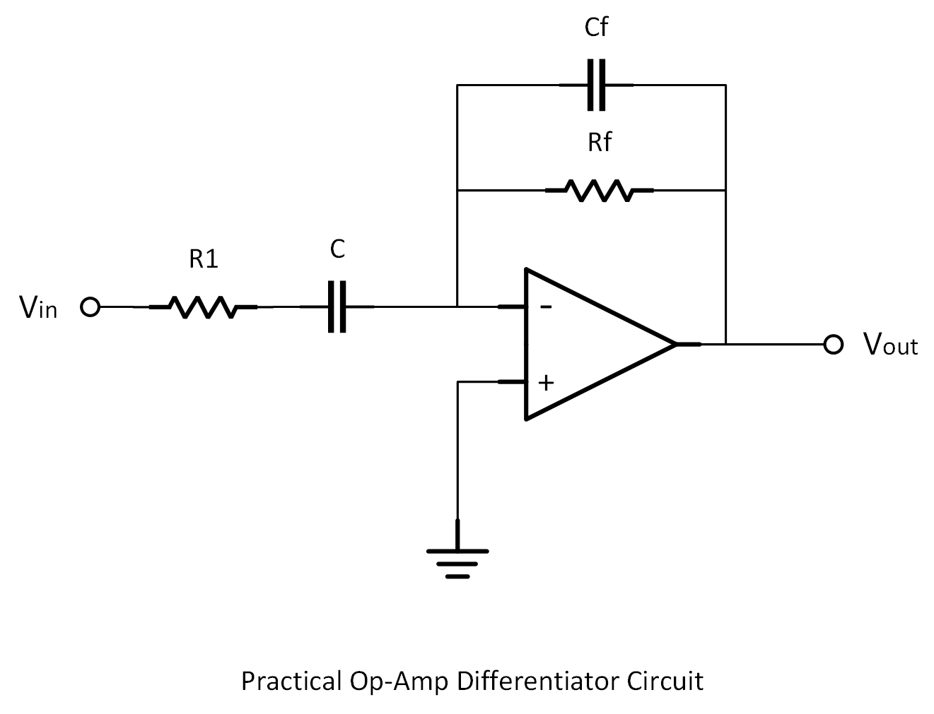
These changes act like a built-in low-pass filter, taming high-frequency gain and making the circuit more stable and usable.
Many designers use Murata ceramic capacitors and Vishay precision resistors for tight tolerance and stable behavior in sensitive analog designs. You might want to consider these things.
3. Op-Amp Bandwidth Limits
No op-amp has infinite bandwidth. At high frequencies, the gain drops off. That’s why it’s important to choose op-amps with high gain-bandwidth products, like Analog Devices’ ADA4898 for high-speed performance or TL072 for budget-friendly designs.
4. Slew Rate Limitations
Op-amps can’t respond instantly to fast changes. Even with a fast square wave at the input, you may see a rounded spike at the output — this is the slew rate limit in action. Choose op-amps with higher slew rates if you’re working with fast signals.
See also
- Explore How a Diode Works in a Circuit.
- What is a Non-Inverting Operational Amplifier (Op-amp) Circuit?
5. Stability Issues
If a differentiator is allowed to amplify very high frequencies without control, the circuit can easily become unstable. Unwanted oscillations or ringing (persistent high-frequency noise) might appear, making the output useless.
Now, we can avoid this by intentionally limiting the high-frequency gain (again using small capacitors and resistors) to stabilize the circuit, even though it slightly compromises the ideal behavior.
6. Power Supply Quality
Noisy or unstable power can inject unwanted signals into your circuit. That’s why regulated power supplies like the Rigol DP832 or Mean Well switching supplies are favored in lab and bench setups. Don’t forget to add bypass capacitors (e.g., 100nF + 10μF) near the op-amp’s power pins.
Differentiator vs Integrator Op-Amps
In analog electronics, differentiators and integrators are two important op-amp circuits that perform fundamental operations based on calculus. These two circuits are like opposites — one highlights change, the other accumulates change over time.
| Differentiator | Integrator |
| Measures rate of change | Measures accumulated value |
| Emphasizes fast changes | Emphasizes slow, cumulative effects |
| Acts like a high-pass filter | Acts like a low-pass filter |
ⓘ Quick Intuitive Analogy
Fun Projects Using Differentiators
- Guitar Pedal Effects
Edge detection circuits using differentiators can trigger audio effects when a sharp pick or strum is detected. Combine with op-amps like JRC4558D (famous in overdrive pedals) to experiment with sound shaping.
- Analog Tachometer
Using a pulse sensor and a differentiator circuit, you can convert position signals (e.g., from rotary encoders) into speed information.
- Earthquake Detector
By combining a vibration sensor with a differentiator, you can build a simple earthquake alarm. Modules like the SW-420 vibration sensor pair well with op-amps like the LM358 for detecting sudden changes.
Next Steps
- Learn more about Op-Amp Comparators.
- Explore what a Voltage Follower (Buffer) is.
Creator and Editor at AnitoCircuits.com based in Toronto