This project guides you through the design and construction of a variable DC power supply that can provide output voltages ranging from 2V to 14V DC, adjustable via a potentiometer. It’s powered from the standard 115V AC, 60Hz wall outlet and is a great bench tool for hobbyists or students working with low-voltage electronic projects.
Project Specifications
| Parameter | Value |
| Input Voltage | 115V AC, 60 Hz |
| Output Voltage | 2 – 14V DC |
| Regulator Type | LM317 Adjustable Linear Regulator |
| Max Output Current | Up to 1.5 A |
| Enclosure | Rectangular Metal Enclosure |
Project Objective
This project aims to create a low-cost, reliable, and adjustable DC power source that can serve as a test supply for electronics circuits. It converts high-voltage AC from the wall into a low, variable DC voltage using a step-down transformer, rectifier, filter capacitors, and an LM317 linear voltage regulator.
This project not only demonstrates circuit design, simulation, and PCB layout but also provides insight into linear voltage regulation and thermal management.
Components
All components for this project were procured from DigiKey. A full Bill of Materials (BOM) is available below:
Bill of Materials (BOM)
| Quantity | Reference designator | DigiKey Part # | Manufacturer Part Number | Description |
| 1 | C1 | 493-1110-ND | UVR1H471MHD | CAP ALUM 470UF 20% 50V RADIAL TH |
| 1 | C3 | P5178-ND | ECA-1HM100 | CAP ALUM 10UF 20% 50V RADIAL TH |
| 2 | J1/J2 | A98472-ND | 4DB-P108-02 | CONN BARRIER STRIP 2CIRC 0.325″ |
| 1 | C4 | 493-1111-ND | UVR1H102MHD | CAP ALUM 1000UF 20% 50V RADIAL |
| 1 | C2 | P5568-ND | ECA-1HHG220 | CAP ALUM 22UF 20% 50V RADIAL TH |
| 6 | D1 – D6 | 1N4001GOS-ND | 1N4001G | DIODE GEN PURP 50V 1A AXIAL |
| 1 | POT | 987-1301-ND | P160KN-0QC15B10K | POT 10K OHM 1/5W PLASTIC LINEAR |
| 1 | R1 | CF14JT1K00TR-ND | CF14JT1K00 | RES 1K OHM 5% 1/4W AXIAL |
| 1 | R2 | CF14JT560RTR-ND | CF14JT560R | RES 560 OHM 5% 1/4W AXIAL |
| 1 | IC1 | 497-1575-5-ND | LM317T | IC REG LINEAR POS ADJ 1.5A TO220 |
| 1 | 283-BK16-HTJ-601I-ND | BK16-HTJ-601I | FUSE HOLDER 1/4″ 10A SLDR TERM | |
| 1 | F4256-ND | 0217001.TXP | FUSE GLASS 1A 250VAC 5X20MM | |
| 1 | Q335-ND | 703W-00/07 | PWR ENT RCPT IEC320-C14 PANEL QC | |
| 4 | WM18353-ND | 191440003 | CONN SPADE TERM 18-22AWG #4 RED | |
| 2 | A27856CT-ND | 3-520406-2 | CONN QC RCPT 14-16AWG 0.250 | |
| 1 | 314-1204-ND | BU-P2269 | CONN DBL BANANA JACK TURRET | |
| 1 | T1 | HM520-ND | 166L12 | PWR XFMR LAMINATED 31.5VA TRANSFORMER |
| 1 | TL451-ND | P006-003 | CORD 18AWG NEMA5-15P – IEC320 3′ | |
| 1 | Sayal Electronics | METAL ENCLOSURE |
Circuit Design and Analysis
Schematic Capture (Fusion 360 Electronics)
I recreated the entire schematic in Fusion 360 Electronics to design and fabricate an efficient PCB (Printed Circuit Board).
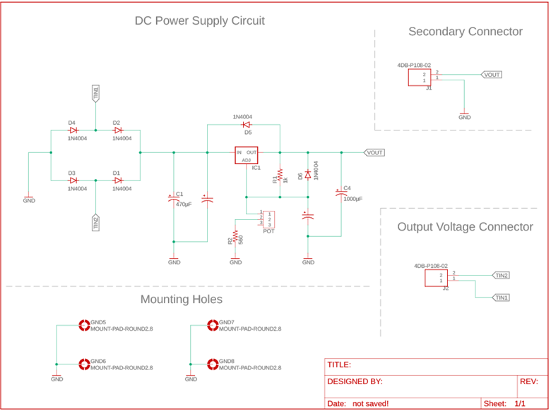
Here, the schematic includes:
Connection from the output of the transformer, followed by:
- Bridge Rectifier to convert AC to DC
- Filtering Capacitors to smooth out ripple
- LM317 Regulator circuit
- Adjustable Potentiometer for output control
- Output terminal connection for connecting test loads
Note: The two filter capacitors (1000µF and 0.1µF) are present in the schematic but were accidentally left unlabeled. Also, if you’re wondering, a diode is placed between the output (OUT) and input (IN) of the LM317 to protect the regulator from damage during shutdown or capacitor discharge.
PCB Design
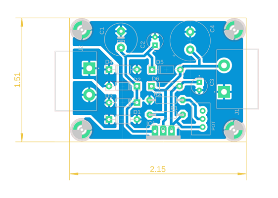
PCB Layout Features
- Board Dimensions: 1.51″ x 2.15″
- Board Shape: Rectangular
- Layer Count: Single-sided (Bottom Layer Only)
- Trace Width: 32 mils (for up to 1.5A current)
- Component Mounting: Through-hole for DIY-friendly soldering
- Material: FR4 copper-clad board
Typically, you send Gerber files generated from the software to a PCB manufacturer or “PCB house.” These files contain essential details such as copper layers, solder masks, silkscreen, and other key design elements. But for this project, I just used my school’s in-house manufacturing facility to obtain a simple PCB.
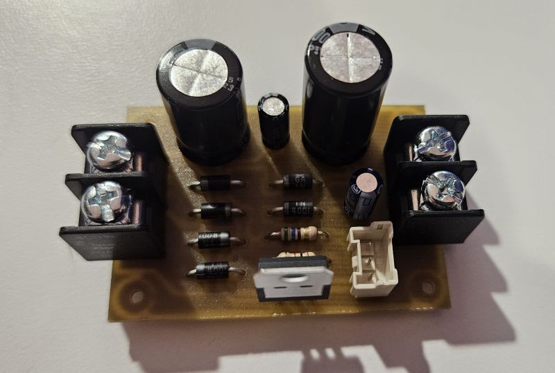
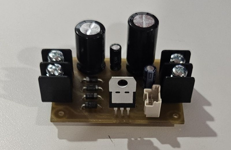
PCB Assembly and Soldering
In my PCB design, the LM317 and filter caps are positioned for optimal thermal performance, and wide traces are used on the power line to reduce voltage drops. Additionally, a heatsink can be attached to the LM317 to handle thermal dissipation.
Design Tips
- Keep high-current paths short and thick.
- Place filter capacitors close to the regulator’s input and output pins.
Parts Assembly
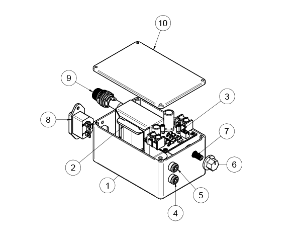
| Parts List | ||
| Item | Qty | Part Number |
| 1 | 1 | Main Enclosure Body |
| 2 | 1 | Transformer Part |
| 3 | 1 | PCB Board |
| 4 | 1 | 4mm Black Banana Terminal |
| 5 | 1 | 4mm Red Banana Terminal |
| 6 | 1 | 19mm POTENTIOMETER KNOB |
| 7 | 1 | Potentiometer2 |
| 8 | 1 | Part 1 |
| 9 | 1 | SF372 10A 250VAC Fuse Holder |
| 10 | 1 | Enclosure Lid |
Before starting the assembly and wiring process, I ensured the enclosure was properly prepared first. This preparation led to a cleaner, safer, and easier assembly, making future troubleshooting more straightforward despite the compact size of the enclosure.
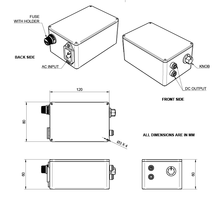
1. First, I marked and drilled holes for all major components within the enclosure, such as the transformer and PCB mounting holes. This included making holes for the voltage adjustment knob, fuse holder, AC input socket/plug, DC output terminals, and ground terminal.
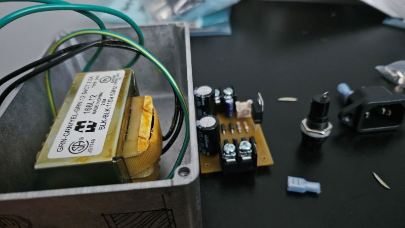
2. After drilling the holes, I first mounted the transformer into the main enclosure. Then, one by one, I installed the PCB assembly and other parts, including the fuse holder, output connectors, ground connector, potentiometer, and AC plug connector.
3. Now I’m ready to wire them. I connected the components according to the schematic. I began by wiring the AC input side, then proceeded toward the DC output side, while observing correct polarity and securely insulating all AC connections.
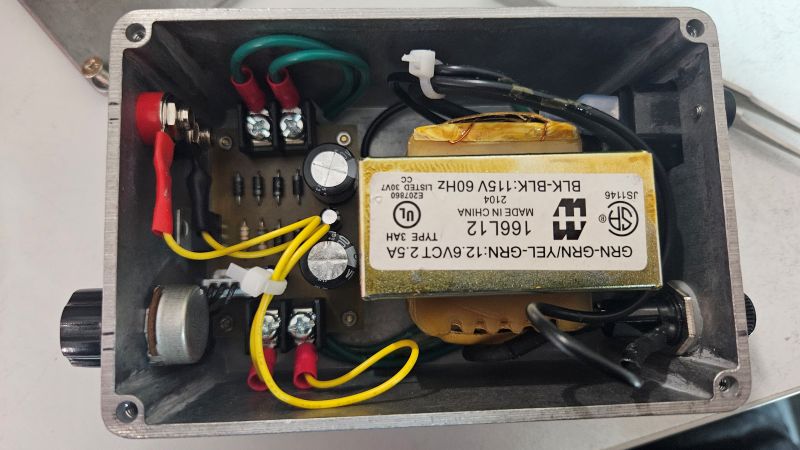
4. The transformer has three output wires — two outer wires and a center-tap (CT). I connected the two outer terminals to the AC inputs of my bridge rectifier (PCB Assembly). The center tap (CT) is connected to the dedicated terminal within the enclosure. Also, I made sure there is a proper grounding between my PCB assembly and metal enclosure.
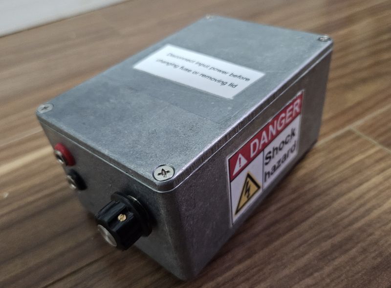
5. Once the wiring is complete, there should be labels for key areas of the power supply. (Here, I forgot to put labels for my DC output and adjustable knob). This step ensures safe usage and clear understanding for anyone who operates or services the unit.
Dimensions
Output Voltage Test
Using a multimeter, I adjusted the potentiometer and measured output voltages ranging from 2V to around 14V under no-load conditions. With a small load (e.g., a 12V fan), the voltage remained stable with minimal ripple thanks to the filtering.
Safety and Reliability Testing
Additionally, after full assembly, my variable DC power supply should undergo a series of validation and stress tests. These ensure the device is electrically safe, mechanically secure, and robust enough for real-world use.
Hi-Pot Test (High Potential Test)
This is to verify that there is sufficient insulation between the AC mains circuitry and the low-voltage DC side or chassis. This is a critical safety test used to detect breakdown or leakage paths.
Drop Test (Mechanical Integrity Test)
Its purpose is to check if the enclosure and internal parts survive a drop from normal bench height (simulating real-world accidents).
Pull Test (Wire and Terminal Strength Test)
This is to ensure all connectors and wire terminations can withstand physical stress and won’t loosen or disconnect under regular use.
Conclusion
This project offers a practical, compact, and effective solution for a bench power supply that’s capable of powering small electronics projects. It’s an ideal first project to learn about:
- AC to DC conversion
- Voltage regulation using LM317
- PCB layout for power electronics
- Safe handling of AC and high-current circuits
Creator and Editor at AnitoCircuits.com based in Toronto