A short circuit occurs when current finds a path with no resistance, flooding the circuit with dangerous levels of current. An open circuit is the opposite. It’s a break in the path that stops current from flowing at all.
These two faults sit at opposite ends of the resistance spectrum. A short circuit has zero (or near-zero) resistance; an open circuit has infinite resistance. Understanding them deeply is foundational knowledge that connects Ohm’s Law, circuit analysis, component behaviour, protection devices, and measurement techniques into one coherent picture.
The Three States of a Circuit
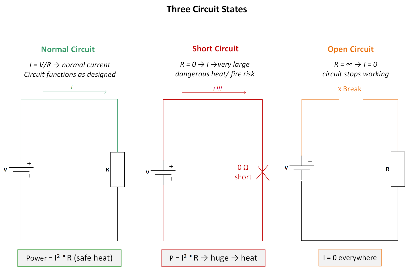
Every circuit can exist in one of three states: normal operation, short circuit, or open circuit. These are the first mental models to reach for when a circuit is not behaving as expected.
Normal operation
In a normal circuit, current flows through the designed resistance path. Ohm’s Law governs everything: I = V / R. Power is dissipated as designed. Everything works as intended.
Short circuit
A short circuit occurs when current finds a path with extremely low or zero resistance, bypassing the intended load entirely. Because I = V / R, and R approaches zero, the current approaches infinity. In practice, it becomes very large, limited only by the internal resistance of the source and the wire resistance.
The word ‘short’ refers to a shortcut, a short path between two nodes that should have a load between them. Current takes the path of least resistance, bypassing everything else.
Open circuit
An open circuit occurs when the conducting path is broken, such as a disconnected wire, a solder joint cracks, a component lifts from a PCB, or a connector works loose. With no path for current, I = 0 everywhere in the loop. The circuit stops working.
The word ‘open’ comes from the idea of an open switch, a gap in the path. Even a microscopic break in a wire creates an open circuit with infinite resistance and zero current.
Short Circuits: The Physics of Danger
Short circuits are the most immediately dangerous fault condition in electronics. When resistance drops to near-zero, the consequences follow directly and rapidly from Ohm’s Law and the power equation.
What Ohm’s Law says
Current during a short circuit:
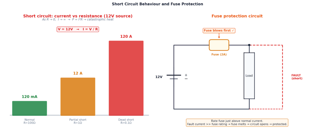
\[ I = \frac {V}{R} \](as R → 0, I → ∞) 12V source, short resistance = 0.1Ω: I = 12 / 0.1 = 120 A. Normal at 100Ω: I = 120 mA. The short carries 1,000× more current.
Power during a short circuit:
\[ P = I^2 R \quad = \quad \frac{V^2}{R} \quad = \quad VI \]At 120A through 0.01Ω wire: P = 120² × 0.01 = 144 W in a wire. That wire will glow, then melt, then potentially ignite.
What actually happens during a short
- Instant surge: large current immediately flows through the lowest-resistance fault path
- Resistive heating: P = I²R heats every conductor in the fault path. Rising with the square of the current
- Insulation damage: wire insulation melts or chars, potentially causing secondary shorts elsewhere
- Component destruction: semiconductors can be permanently destroyed in microseconds by overcurrent
- Fire risk: hot wires and burning insulation can ignite nearby materials if the fault is sustained
- Source damage: even the power source itself can be damaged. Batteries can rupture or vent
Common causes of short circuits
- Solder bridges: a droplet of solder accidentally connecting adjacent PCB pads. One of the most common causes in DIY electronics
- Damaged wire insulation: cracked, frayed, or melted insulation, allowing bare conductors to contact each other
- Component failure: capacitors and MOSFETs frequently fail short-circuit when overvoltaged or overheated
- Conductive contamination: flux residue, moisture, metallic debris, or dropped screws bridging terminals
- Reversed polarity components: inserting an electrolytic capacitor or diode backwards can cause immediate short-circuit failure
- ESD damage: electrostatic discharge can punch through gate oxides in MOSFETs, creating a permanent D-S short
Protection devices against short circuits
Fuses
A fuse contains a thin metal element calibrated to melt when current exceeds its rated value, creating an open circuit and stopping fault current. Fuses are single-use. Choose a rating at 125–150% of normal operating current: too high and the circuit is unprotected, too low and the fuse trips during normal operation.
Circuit breakers
A circuit breaker performs the same function as a fuse, but can be reset after tripping. A bimetal strip or electromagnetic mechanism opens the circuit on overcurrent. Breakers are used in household wiring, automotive systems, and industrial equipment.
Polyfuses (resettable fuses)
PTC (Positive Temperature Coefficient) thermistors whose resistance rises sharply when heated by overcurrent. They self-reset when cooled. Widely used in USB ports, battery packs, and PCB protection circuits.
Current-limiting resistors
The simplest protection for low-power loads like LEDs. A series resistor limits the maximum current even in a fault condition. Calculate the value as: R = (Vsupply − Vforward) / Idesired.
⚠ Caution
Never wire an LED directly to a voltage source without a series resistor. Even a small variation in forward voltage or temperature will cause runaway current increase. The resistor is not optional — it is what makes the circuit safe.
Open Circuits: When the Path Breaks
An open circuit is the quiet counterpart to the dramatic short. Where a short floods the circuit with current, an open silently stops it. The symptoms are often less immediately obvious (a circuit that simply does not work), but open circuits are equally important to understand and diagnose.
What Ohm’s Law says
Current in an open circuit:
\[ R = \infty \quad \Rightarrow \quad I = \frac{V}{\infty} = 0\ \text{A} \]No current flows. Zero power dissipated. The circuit is dead. However — voltage CAN still exist across the open gap. Full supply voltage appears across an open switch or broken wire.
The floating node problem
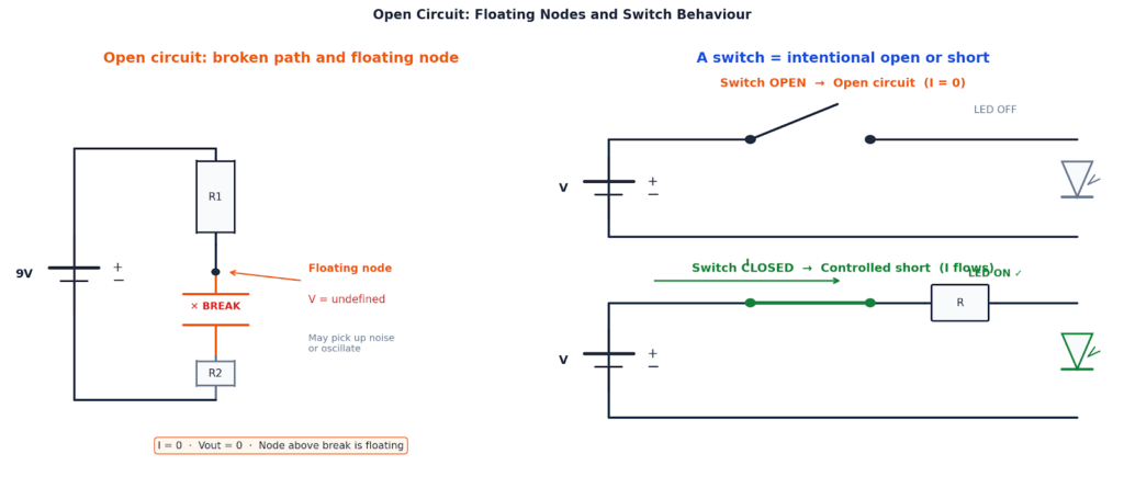
One of the most important consequences of an open circuit is the floating node. When a node loses its connection to a defined voltage through a broken path, its voltage becomes undefined and uncontrolled.
A floating node can:
- Pick up interference: capacitive coupling from nearby conductors, power wiring, or RF signals. The node acts as an antenna
- Oscillate: In CMOS circuits, a floating input can oscillate between logic levels, causing erratic behaviour and excess power consumption
- Trigger latch-up: In CMOS ICs, floating inputs can trigger a destructive latch-up condition with excessive current draw
- Give false readings: a voltmeter on a floating node may display various voltages due to the meter’s own input impedance loading the node
⚠ Critical design rule:
Never leave a digital logic input floating. Unused CMOS inputs must be tied to VCC or GND through a pull-up or pull-down resistor (typically 10 kΩ). A floating digital input is an open circuit that will behave unpredictably — and may damage the IC.
Voltage across an open circuit
While no current flows through an open circuit, voltage can appear across the open gap. If you break a wire in a series circuit with a 9V battery and a resistor, the full 9V appears across the break. The battery still pumps voltage. This is why an open high-voltage circuit can still be lethal.
Voltage divider example: in a series circuit with R1 on top and R2 on the bottom, if R2 goes open circuit, the output node rises to the full supply voltage. No current flows through R1, so no voltage drops across it. If R1 opens, the output drops to zero. Each component’s failure mode produces a distinct measurable symptom.
Common causes of open circuits
- Cold solder joints: look connected visually but have a high-resistance or fractured bond. One of the most difficult faults to find
- Cracked PCB traces: mechanical stress, vibration, or thermal cycling can crack thin copper tracks
- Lifted pads: excessive rework heat can lift a pad from the substrate, breaking the trace connection
- Corroded contacts: oxidation on connector pins or switch contacts creates high resistance that eventually becomes a full open
- Broken component leads: vibration fatigue or mechanical shock can fracture leads at the body entry point
- Blown fuse: a correctly functioning protection event — the fuse creates an intentional open to stop fault current
A switch is a controlled open/short circuit
A mechanical switch, relay, transistor, or MOSFET used as a switch is simply a device that creates a controlled open circuit (off state = infinite resistance = zero current) or a controlled short circuit (on state = near-zero resistance = current flows). Every light switch, relay coil, and logic gate output exploits this fundamental duality.
Component Failure Modes and Detection
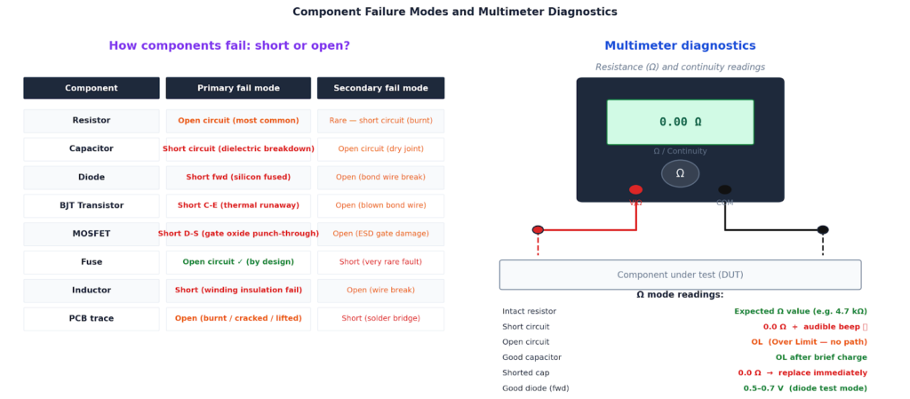
Different electronic components have characteristic failure modes. They tend to fail either as a short or as an open, depending on their construction and the nature of the fault. Knowing which way a component typically fails is enormously useful for targeted troubleshooting.
Using a multimeter to find faults
Resistance mode (Ω) — power off
Measure across a component or between two nodes with power removed:
- Expected resistance: component is intact
- 0.0 Ω or near-zero: short circuit — unexpected conduction path present
- OL (over limit): open circuit — no conducting path between probe points
Continuity mode — power off
The fastest check. The meter beeps when it detects a low-resistance path (typically < 30 Ω):
- Verify wire continuity: probe each end — beep means intact, silence means broken wire
- Check solder joints: probe both sides of a joint — beep confirms good connection
- Hunt solder bridges: probe adjacent IC or connector pins — any unexpected beep = short circuit
- Trace PCB tracks: probe along a trace to find the location of a crack or lifted pad
Voltage mode (V) — power on
Short circuit symptom: voltage collapses to near 0V across the load. All voltage is being dropped across the source’s internal resistance. Current is high.
Open circuit symptom: full supply voltage appears at the open break point (no current, no drop). Downstream of the break reads 0V.
ⓘ Pro tip!
Voltage measurements in a live circuit reveal intermittent faults that resistance measurements miss. A cold solder joint may test fine when cold and dry but open when warm or under mechanical stress. Probe while flexing the PCB or applying gentle pressure to connectors.
Thévenin’s Theorem: Short and Open Circuits in Analysis
Short circuit current and open circuit voltage are not just fault conditions. They are the two measurements that define Thévenin’s theorem. Every linear circuit, no matter how complex, reduces to a single voltage source (Thévenin voltage Vth) in series with a single resistance (Thévenin resistance Rth).
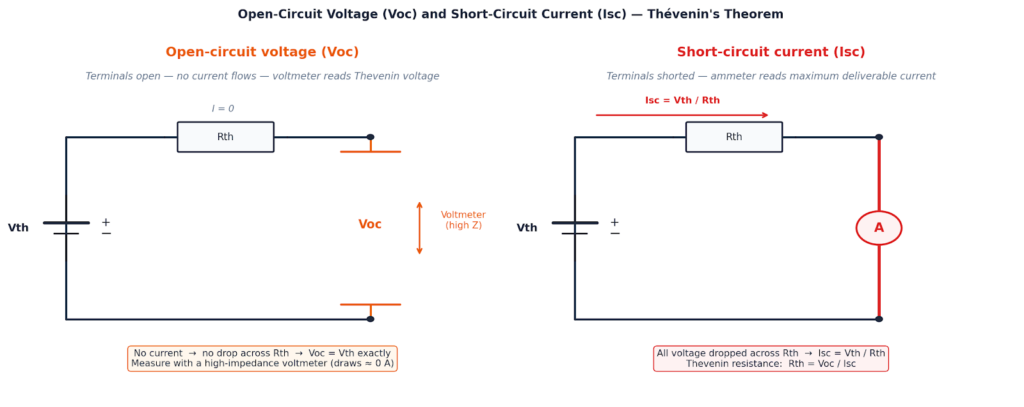
Open-circuit voltage (Voc)
Disconnect the load and measure the voltage at the output terminals. Since no current flows, there is no voltage drop across the Thévenin resistance. The full Thévenin voltage appears directly at the terminals.
Open-circuit voltage:
\[ V_{oc} = V_{th} \]No current → no drop across Rth → terminal voltage equals the Thévenin source voltage exactly. Measure with a high-impedance voltmeter.
Short-circuit current (Isc)
Short the output terminals together through an ammeter and measure the current. The only resistance limiting this current is the internal Thévenin resistance Rth.
Short-circuit current:
\[ I_{sc} = \frac{V_{th}}{R_{th}} \]All voltage dropped across Rth. This is also the Norton equivalent current. Use a current-limited supply or add a known series resistor when measuring real sources to protect the meter.
Finding Thévenin resistance
Thévenin resistance:
\[ R_{th} = \frac{V_{oc}}{I_{sc}} \]The internal resistance of any source can be determined from two simple measurements, no detailed circuit analysis required. For a battery, this resistance corresponds to its internal resistance (). For a power supply, it is referred to as the output impedance. In the case of an op-amp output, this value is typically extremely low, often in the milliohm range.
For example, you can assess battery health using its Thévenin equivalent. A fresh 9 V battery might measure 9.2 V open-circuit and drop slightly to 8.7 V under a 100 mA load. This gives an internal resistance of
, which is typical for a healthy battery.
In contrast, an ageing battery may still show 9.0 V with no load, but collapse to 5.5 V under the same 100 mA load. Its internal resistance becomes
, indicating a significant degradation, which is too high to reliably power most circuits.
Real-World Troubleshooting Scenarios
Scenario 1: LED will not light
- Check polarity first: LEDs are polarised — flip it and try again
- Check in diode test mode: should read 0.5–3.2V forward; OL means LED is open (dead)
- Check the series resistor: OL in resistance mode means the resistor is open (burnt out)
- Check supply voltage: 0V at the input means an open circuit upstream — check cable, connector, battery
- Check for solder bridges: probe adjacent pads for 0Ω beep — any unexpected continuity = short
Scenario 2: Microcontroller board will not power up
- Measure supply at power pins: 0V means open circuit upstream — check USB cable, connector, polyfuse
- Measure current draw: excessive current (well above rated) = short circuit on the board — check near power regulation IC
- Feel for warmth: components near a short circuit will become warm within seconds of applying power
- Check the polyfuse: some boards have a polyfuse on the USB input that trips and looks like an open circuit
Scenario 3: Finding a solder bridge
- Visual inspection first: use a magnifying glass or phone macro — bridges are often visible on dense IC pads
- Probe adjacent pins: any unexpected beep between pins that should be independent = solder bridge
- Work from the schematic: check pins that should be logically independent first
- Fix with solder wick: place wick over the bridge, apply heat — excess solder is drawn away by capillary action
Always check for solder bridges before powering a new PCB for the first time. A two-minute continuity sweep of IC pins, power rails, and adjacent traces is far quicker than diagnosing a destroyed component after power-up.
Creator and Editor at AnitoCircuits.com based in Toronto