Capacitor charging revolves around the transfer of electrical energy to the capacitor, resulting in an increase in voltage across its terminals.
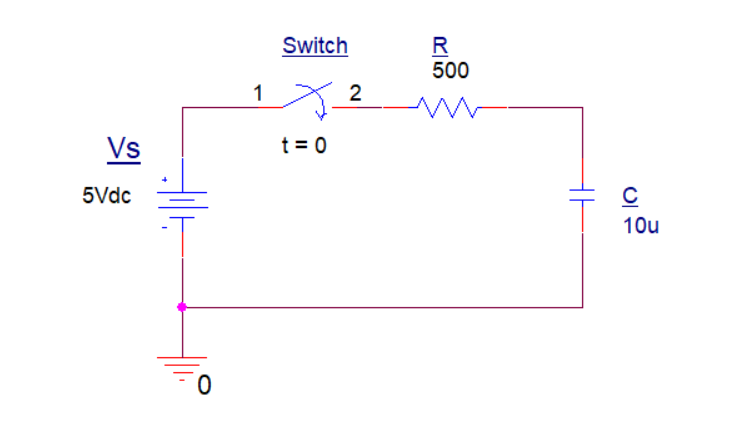
The figure below shows a capacitor (C) and a resistor (R) connected in series to form an RC Charging Circuit. This circuit is connected to a DC battery supply (Vs) through a mechanical switch.

Now, when the switch is closed at t=0 (assuming the capacitor is fully discharged), the capacitor begins the charging process by accumulating charge on its plates. This accumulation of charge leads to a build-up of a potential difference across its terminals.
The capacitor then stops charging when this potential difference equals the voltage of the connected power source.
Charging Time Constant (RC Time Constant)
During the charging process, the voltage across the capacitor gradually increases until it reaches the level of the source voltage.
Mathematically, this charging process is often described using the RC time constant, tao (τ):
\[ \large τ = R \times C \]
τ = Time Constant (seconds)
V = Applied Voltage to the Capacitor (volts)
R = Resistance (ohms)
C = Capacitance (farads)
The time constant represents the time it takes for the voltage across the capacitor to reach approximately 63.2% of the source voltage. After about five times the time constant, the capacitor is considered fully charged.
Capacitor Charging Curve
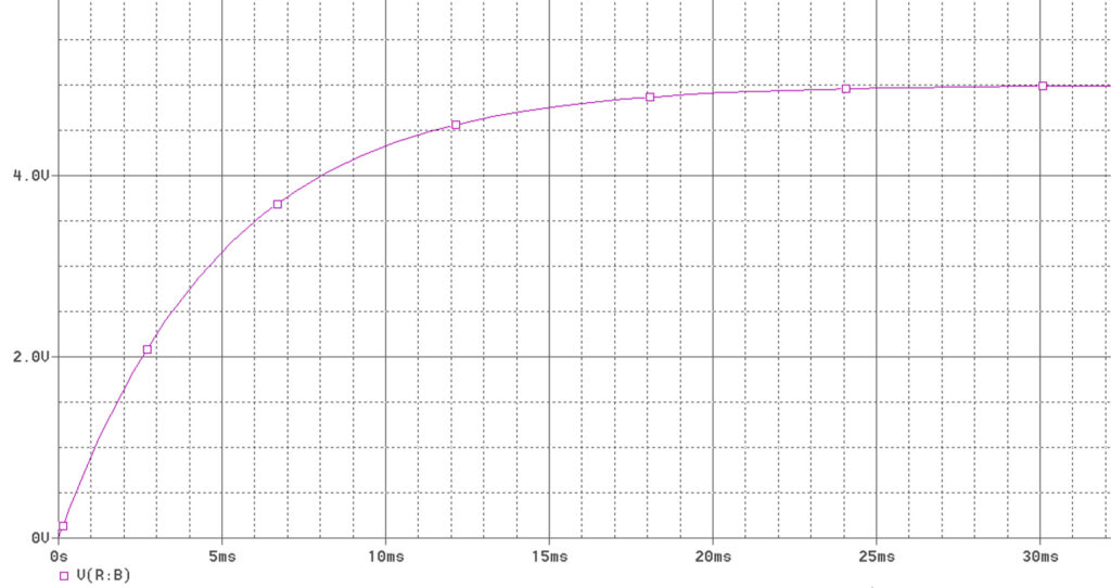
The charging curve shows the voltage across the capacitor as time ticks away. At first, it’s like an exponential buildup, revealing the gradual rise of the capacitor voltage towards the source voltage.
You can visualize a capacitor’s charging and discharging curves by simulating the circuit. Several tools are available, ranging from simple to more advanced options but in this example, I’m using OrCAD Capture to visualize the curve.
The figure below (figure 2), illustrates the charging curve of the capacitor in the given RC circuit above. The Analysis type is set to Time Domain (Transient) and run time to 30 ms. The initial charge of the capacitor is also set to zero.

The x-axis typically represents the time variable in seconds or milliseconds, depending on the scale of the experiment or simulation. The y-axis represents the voltage across the capacitor at any given time.
From the RC circuit above, given that R = 500 ohms and C = 10 μF, I can calculate the one-time constant:
\[ τ = R \times C = 500(10 \times 10^-6) \]
\[τ = 5 \text{milliseconds} (ms) \]
To display the capacitor voltage at t = 5 ms from the curve, I’m going to use the “cursor search function” of the simulator window in my OrCAD software.

Here, from the cursor window, we can see that Vc = 3.1597 Volts at t = 5 ms. Please note that this potential difference represents 63.2% of its steady-state value. It indicates that the capacitor has charged significantly, but it is not at its maximum voltage.
The charging process then continues, and it will take additional time constants until the capacitor approaches full charge.
But how long does it take for the capacitor to fully charge?
In practical terms, the rule of thumb that considers the capacitor as effectively fully charged over the charging period is after approximately 5 time constants (5τ).
So, from our example, let’s determine the time at 5τ:
\[ 5τ = 5 \times (500(10 \times 10^-6)) = 25 ms \]
Using again the “cursor search function” of the simulator window, we can display the capacitor voltage at this specific time.

We can see that Vc = 4.9667 Volts at t = 25 ms. From the curve figure above, the curve shows that it starts to stabilize at t = 25 ms. At this point, the capacitor is considered fully charged, and further changes in time have minimal impact on the voltage across the capacitor.
Calculating Capacitor Voltage at any given Time
The formula to calculate the voltage across a capacitor at any given time during the charging process is expressed using an equation based on the exponential charging curve.
\[ \large V(t) = V_{source} \times (1-e^{-\frac{t}{RC}}) \]
Where:
- V(t) is the voltage across the capacitor at time t.
- Vsource is the voltage of the source.
- R is the resistance in ohms.
- C is the capacitance in farads.
- e is the mathematical constant (approximately 2.71828).
In this formula:
From the RC circuit above (figure 1), we can determine the capacitor voltage at any given time using the formula.
Given values:
- Vsource = 5V
- R = 500 ohms
- C = 10 μF
| Time Constant | t(s) | Vc | Percentage |
| τ | 5 milliseconds (ms) | 3.161 V | 63.2 % |
| 2 τ | 10 ms | 4.323 V | 86.5 % |
| 3 τ | 15 ms | 4.751 V | 95.0 % |
| 4 τ | 20 ms | 4.908 V | 98.2 % |
| 5 τ | 25 ms | 4.966 V | 99.3 % |
Does a capacitor reach a 100% charging state?
A capacitor in an RC charging circuit never fully reaches a 100% charged state. The charging process follows an exponential curve rather than a linear one.
In Theory, as time (t) approaches infinity, the term e-t/(RC) approaches zero, making V(t) approach Vsource. Mathematically, it approaches but never quite reaches the maximum voltage (or 100% fully charged state).
However, for practical purposes, a capacitor is often considered to be fully charged after a certain point. Commonly, when the voltage across the capacitor has reached approximately 99.3% of the maximum voltage. This corresponds to around 5 time constants in the charging process.
So, while the capacitor does not technically reach 100% due to the nature of exponential growth, for many applications, it’s effectively fully charged after a certain duration of the charging process.
Next Step
- Learn more about Capacitors.
- Explore Capacitors in Series and Parallel.
Creator and Editor at AnitoCircuits.com based in Toronto
