Current, voltage, and resistance are the three important electronics concepts that form the foundation of understanding how circuits operate. Current represents the flow of electric charge through a conductor, voltage is the electrical potential difference that drives this flow, and resistance is the property of a material that opposes the flow of current.
While it sounds more theoretical, learning these concepts is very important, especially when designing circuits, troubleshooting electrical systems, or performing measurements with tools like multimeters.
What is Current
In a typical wire, there are these charged particles called “electrons” moving through the material. They are described as a measure of electric charge. The movement, however, of this charge is known as “electric current.”
So, current refers to the flow of electric charge through a conductor or circuit. It’s measured in amperes (A), which is the amount of charge flowing past a point on the circuit per unit of time. You often see it represented by the symbol “I”.

In conventional current theory, the direction of current flow is from the positive terminal to the negative terminal of a voltage source, opposite to the direction of electron flow. This convention simplifies circuit analysis and is widely used in electrical engineering.
Types of Current
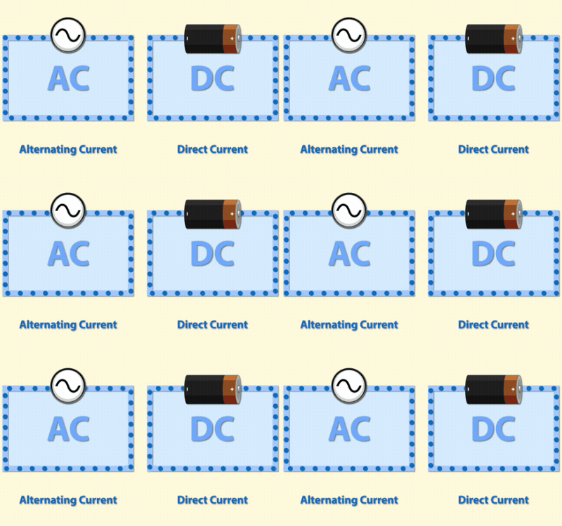
There are two types of current that you will likely encounter. Direct Current (DC), which flows in one direction only, and Alternating Current (AC) which changes direction periodically.
What is Voltage
Voltage is a measure of the electric potential difference between two points in a circuit. It is typically represented by the symbol “V” and is measured in volts (V).
Voltage is often compared to the force that drives water through a pipe. For example, you can think of voltage as the force that drives electrons through a conductor, much like water flowing through a pipe. The greater the voltage, the more effectively it can push the electrons in the circuit. This can be compared to the pressure of water in a pipe, where higher pressure can push water more effectively through the pipe.
Voltage Sources
It is important to note that voltage alone is not enough to power a circuit. In addition to voltage, a circuit needs a source of current to provide a continuous flow of electrons.

To provide a potential difference in a circuit, you need a power source, such as batteries, solar cells, or power supplies. However, note that these are common sources of DC (Direct Current) voltage.
If your circuit requires an AC (Alternating Current) voltage, you need to obtain a power source that supplies alternating current. Since most electronic circuits are powered with low voltages, you can’t directly connect your circuit to a wall outlet without using a transformer or power adapter.
When working with analog circuits, like active filters, RCL circuits, or RF amplifiers, we often use specialized signal generators to produce AC voltage waveforms of specific frequencies, amplitudes, and wave shapes.
AC and DC Voltage
Speaking of AC and DC voltage, these are two types of electrical voltage that differ in their waveform and characteristics.

Here’s what you need to know. DC voltage maintains a constant polarity and voltage level over time. DC voltage is mainly used in electronic circuits where a steady and unidirectional flow of current is required, such as digital systems, solar power, etc.
On the other hand, AC voltage alternates between positive and negative polarities in a sinusoidal waveform.
What is Voltage Drop
Voltage drop refers to the decrease in voltage across a component due to the encountered resistance.
For example, in a series circuit, you have four resistors connected to a voltage source. As the current flows through each resistor in turn, it experiences resistance and forces the total voltage to be distributed across each resistor.
Technically, this voltage drop represents the loss of potential energy as the current works to overcome the resistance. That’s why if you notice, the total voltage drop across all resistors in series is the sum of the individual drops, which equals the total voltage supplied by the source.
What is Resistance
Lastly, resistance is the property of a circuit that resists the flow of electric current. It is expressed in “ohms” and represented by the Greek letter omega (Ω).
In basic electrical circuits, resistors are commonly used to introduce resistance. They are passive components that limit or regulate the flow of electric current to achieve desired levels.
By introducing resistance, you can control the voltage and current in a circuit.
With that said, also note that resistance is introduced to protect sensitive components, such as LEDs, Integrated circuits (ICs), etc. from excessive current or create voltage drops necessary for these certain components.
The Relationship of Voltage, Current, and Resistance (Ohm’s Law)
The relationship between voltage, current, and resistance is described by Ohm’s Law, one of the fundamental principles of electricity in electrical circuits.

Ohm’s Law states that the current (I) flowing through a conductor between two points is directly proportional to the voltage (V) across the two points and inversely proportional to the resistance (R) of the conductor.
Mathematically, it can be expressed as:
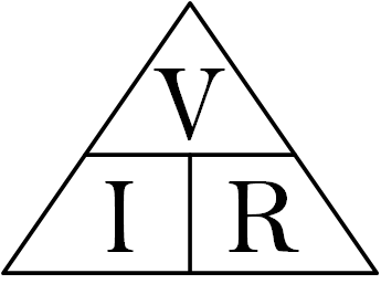
\[I =\frac{V}{R}\]
For instance, if we have a high voltage and low resistance, we’ll get a big current. If the voltage stays the same but the resistance goes up, the current will go down.
We just rearranged the equation depending on the unknown and given quantities.
For example, if the voltage is unknown but the current and resistance are given, you can find the voltage by using this equation:
\[V=IR\]
Similarly, if you want to calculate the resistance of a given circuit or component, you can do it with this equation:
\[R =\frac{V}{I}\]
Kirchhoff’s Current Law
When working with a circuit that has multiple branches, Ohm’s Law alone may not be sufficient to analyze the current in each branch of the circuit.
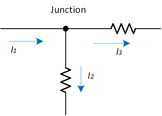
In such cases, we can rely on Kirchhoff’s Law, which states that the total current entering a junction in a circuit is equal to the total current leaving the junction. This principle is also important for understanding and analyzing complex electrical circuits.

As we can see in the figure above, I1 is the current entering the junction while I2 and I3 are the currents that are leaving. Therefore, based on Kirchhoff’s Current Law, I1 = I2 + I3.
Creator and Editor at AnitoCircuits.com based in Toronto
