Unlike bipolar junction transistors (BJTs), which control current using current, FETs control current using an electric field. This distinction also makes them integral to a variety of electronic applications because of their high input impedance and low power consumption.
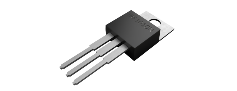
What is a Field Effect Transistor?
A Field Effect Transistor (FET) is an electronic component or device with three main terminals: the Source, Drain, and Gate.
- Source (S): The terminal through which carriers (electrons or holes) enter.
- Drain (D): The terminal through which carriers leave.
- Gate (G): The terminal where voltage is applied to control the current flowing from the source to the drain.
- Body (B): The substrate on which the FET is built, often connected to the source in many applications.
The way how they work is that they control the flow of electric current between the source and drain by applying a voltage to the gate. This voltage generates an electric field that regulates how easily current flows through the channel between the source and drain.
FETs also primarily control the flow of a single type of charge carrier (either electrons or holes), unlike Bipolar Junction Transistors (BJTs), which manage both types.
Types of FETs
There are several types of FETs, but the two most common are:
- Junction Field Effect Transistor (JFET)
- Metal-Oxide-Semiconductor Field Effect Transistor (MOSFET)
Junction Field Effect Transistor (JFET)
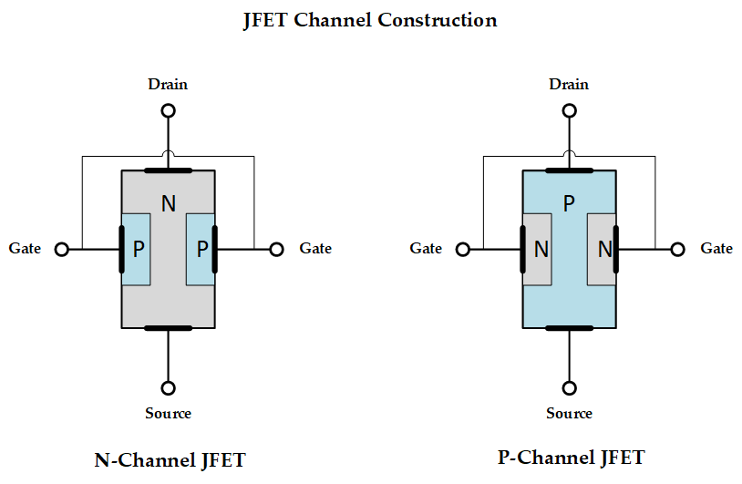
The JFET is the simpler of the two. It has a channel of semiconductor material (either n-type or p-type) through which current flows. The gate is formed by a p-n junction, where a reverse bias voltage at the gate controls the width of the channel, preventing the current.
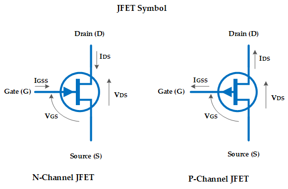
- N-channel JFET: Here, the channel is made of n-type material, and current flows via electrons. A negative voltage applied to the gate reduces the width of the channel and controls the current.
- P-channel JFET: The channel is made of p-type material, and the current is controlled by applying a positive voltage at the gate, which reduces the flow of holes in the channel.
The gate-source junction is reverse-biased, so the input impedance is very high, often in the range of several megaohms. JFETs are “normally ON” devices, meaning they conduct when there is no voltage applied at the gate. To turn them OFF, you must apply a reverse voltage at the gate.
Metal-Oxide-Semiconductor Field Effect Transistor (MOSFET)
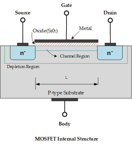
The MOSFET is the most widely used type of FET, particularly in digital and power applications. MOSFETs have an insulated gate, which makes them capable of being controlled with very little power. The gate is separated from the channel by a thin layer of oxide, and its capacitance plays a significant role in controlling the transistor.
Two Types of MOSFETs:
- Enhancement mode (E-MOSFET): These are normally off devices. A positive gate voltage is needed to turn on an n-channel MOSFET, and a negative gate voltage is required to turn on a p-channel MOSFET.
- Depletion mode (D-MOSFET): These devices are normally on, and applying a voltage at the gate depletes the channel, reducing the current flow.
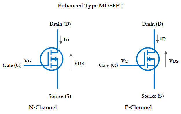
MOSFETs can be categorized further based on the type of semiconductor in the channel.
- N-channel MOSFET: Current flows via electrons. These are faster and have lower on-state resistance compared to p-channel MOSFETs.
- P-channel MOSFET: Current flows via holes. While they are slower and have higher resistance, they are still useful in certain circuits, particularly in complementary MOS (CMOS) logic circuits.
They are known for their extremely high input impedance, typically greater than 109 Mega ohms, which makes them highly resistant to electrical flow. They also feature very fast switching speeds, making them ideal for digital circuits such as designing switches and logic gates.
And lastly, MOSFETs are generally more efficient compared to JFETs, especially in power electronics applications because they consume low power in both switching and steady-state operations.
FET Characteristics and Advantages
FETs are favored in many applications for several reasons.
- High input impedance: This makes FETs ideal for amplifier circuits, especially where the source impedance is high.
- Low power consumption: FETs consume almost no current in the gate, leading to very low power dissipation in control circuits.
- Fast switching speed: MOSFETs, in particular, can switch on and off very quickly, making them useful in high-frequency applications such as RF amplifiers, and in digital circuits where fast logic transitions are necessary.
- Thermal stability: FETs have a negative temperature coefficient, meaning as the temperature increases, the current decreases slightly. This self-regulating feature helps prevent thermal runaway, a problem more common in BJTs.
FET Applications
There are many reasons why FETs are used in a wide range of applications. Their unique characteristics make them prevalent in various electronic devices.
- High-Input Impedance Amplifiers: FETs are commonly used as input amplifiers for oscilloscopes, electronic voltmeters, and other measuring and testing equipment.
- RF Amplifiers: FETs are employed in RF amplifiers for FM tuners and communication equipment because they offer low noise levels, which is crucial for signal clarity.
- Voltage-Controlled Resistors: In applications like operational amplifiers and tone controllers, FETs serve as voltage variable resistors (VVRs) due to their voltage-controlled operation.
- Mixer Circuits: FETs are found in mixer circuits in FM and TV receivers, as well as communication systems, because they produce low intermodulation distortion, improving signal quality.
- Digital Circuits: MOSFETs, in particular, dominate the world of digital electronics. Complementary MOS (CMOS) technology, which uses both n-channel and p-channel MOSFETs, is the backbone of microprocessors, memory chips, and other integrated circuits.
Challenges with FETs
While FETs are incredibly versatile, they also have limitations. MOSFETs, in particular, are highly sensitive to electrostatic discharge (ESD) due to the thin oxide layer in the gate, requiring careful handling to prevent damage. Additionally, the input capacitance of MOSFETs can limit their performance at very high frequencies, leading to slower switching times and losses in power applications.
Although FETs are more thermally stable than BJTs, excessive heat can still degrade their performance. This is why you often see them equipped with heat sinks in power amplifiers to manage thermal issues effectively.
FETs Used in Various Circuits
| Part Number | Description |
| 2N7000 | N-channel MOSFET, commonly used for low-power switching applications |
| BS170 | N-channel MOSFET for low-power switching and signal amplification |
| IRF540N | N-channel MOSFET, widely used for high-power switching applications |
| IRFZ44N | N-channel MOSFET, popular for high-current, low-voltage switching |
| IRLZ44N | Logic-level N-channel MOSFET for microcontroller-driven circuits |
| 2N5457 | N-channel JFET, low-noise, used in analog and RF applications |
| BSS138 | N-channel MOSFET, used for logic-level switching in digital circuits |
| SI2302 | N-channel MOSFET for low-power, low-voltage switching applications |
| SI2305 | P-channel MOSFET for low-voltage, low-power switching |
| IRLB8721 | N-channel MOSFET with low R_DS(on), used for efficient power switching |
| STP55NF06 | N-channel MOSFET, commonly used in power electronics and motor drivers |
| IRF9540N | P-channel MOSFET for high-side switching and power applications |
| FDN304P | P-channel MOSFET, often used in low-power, high-side switching |
| AO3400 | N-channel MOSFET, commonly used in power switching and DC-DC converters |
| AO3401 | P-channel MOSFET for low-voltage switching applications |
| ZXM61P03F | P-channel MOSFET for battery management and low-voltage switching |
Creator and Editor at AnitoCircuits.com based in Toronto
