You can play the audio version of this article.
This podcast episode discusses the fundamentals of diodes, including:
Diodes are essential and widely used components in electronics. They play a pivotal role in regulating current flow and significantly influence the behavior and functionality of electronic and electrical systems.
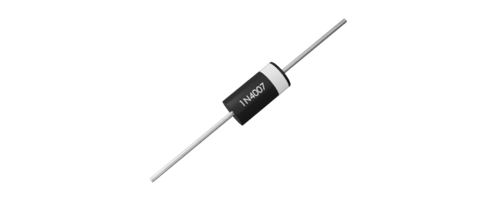
Their ability to allow current to pass in one direction while blocking it in the other makes them indispensable in various applications, from power supplies to signal processing, etc.
In this article, we will explore the core principles of diodes, their function in preventing reverse currents, and how they are applied in circuits, such as rectifiers.
Understanding the Basics of Diodes
A diode is a two-terminal electronic component that primarily conducts current in one direction. It has an anode (+) and a cathode (-).
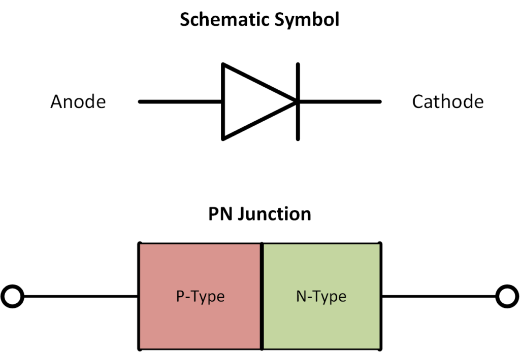
At the heart of a diode is a semiconductor material, typically silicon or germanium, that is doped with impurities to create two distinct regions: an n-type and a p-type.
The p-type semiconductor is rich in holes (positive charge carriers), while the n-type semiconductor is rich in electrons (negative charge carriers). This structure forms what is called a p-n junction.
- P-type: Doped with elements (like boron) that create a deficiency of electrons, resulting in “holes.”
- N-type: Doped with elements (like phosphorus) that contribute excess electrons.
When these two materials are brought together, the electrons from the n-type side migrate toward the p-type side, recombining with holes. This forms a depletion region at the junction, which acts as an insulating layer that prevents current flow until the diode is forward-biased.
Biasing (Forward and Reverse)
Biasing refers to the method of applying a voltage to a device, such as a diode or transistor, to control its operation. Biasing determines whether the device is in a conducting or non-conducting state.
Forward Bias
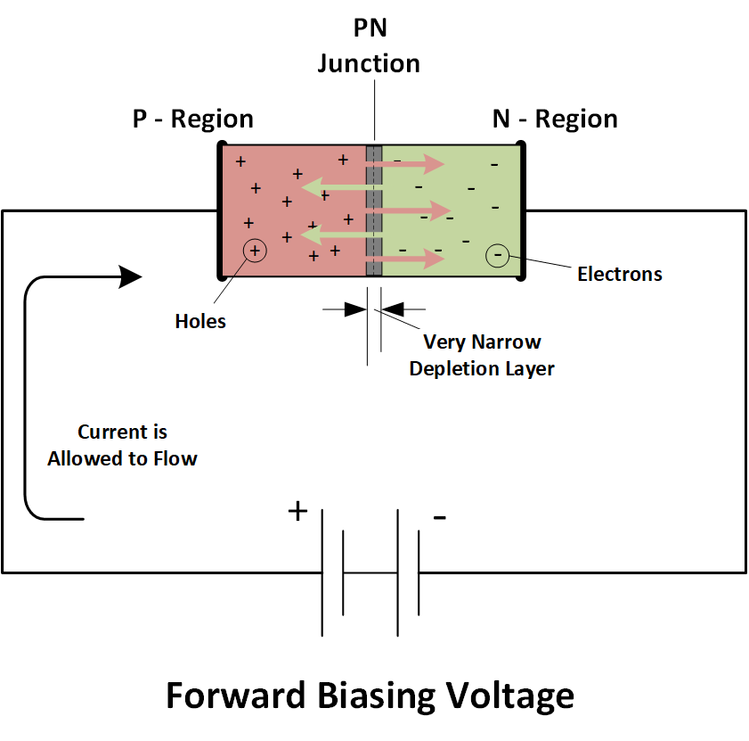
For example, when a forward bias (positive voltage on the p-side and negative on the n-side) is applied to the diode, the depletion region at the junction narrows. And once the external voltage surpasses the forward voltage threshold (the diode’s forward voltage drop), electrons move from the n-region toward the p-region, across the junction. At the same time, holes also moves from the p-region to the n-region.
This movement of charge carriers constitutes an electric current. So, in this case, the diode acts like a closed switch, which allows current to pass through it.
Reverse Bias
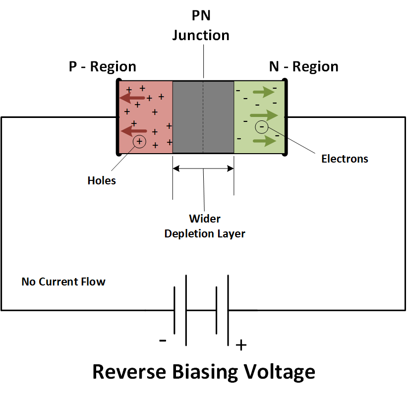
In contrast, when a reverse bias (negative voltage on the p-side and positive on the n-side) is applied to the diode, the depletion region widens. This increased width creates a stronger barrier that prevents the electrons and holes from moving across the junction. As a result, very little current flows—typically a tiny leakage current.
The diode remains in this non-conducting state (the diode acts as an open switch) as long as the reverse voltage stays below the diode’s breakdown voltage threshold.
In addition, if the reverse voltage exceeds this threshold, the diode will enter reverse breakdown. This allows significant current to flow, potentially damaging the diode, unless the diode is designed to operate in this region, like a Zener diode.
Diodes in Preventing Reverse Current
One of the “not so popular” but most vital functions of diodes is their ability to prevent reverse current.
In certain circuits, particularly in power supply systems, the output voltage may briefly exceed the input voltage, leading to a reverse current that can potentially harm sensitive components. Diodes are normally used to prevent this flow and safeguard the circuitry as they function as one-way gates.
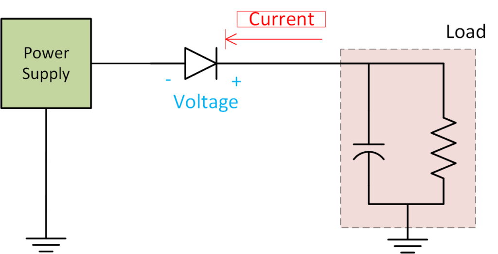
Diodes are more affordable and easier to use than power transistors like FETs, making them ideal for high-voltage, low-current applications. However, they introduce a forward voltage drop (around 0.6-0.8V), which can reduce battery life, limit supply voltage, and lower the power circuit’s efficiency.
Schottky diodes, in particular, are commonly used for this purpose due to their fast-switching speed and low forward voltage drop. One thing to consider, however, is that it not only comes at a higher cost but also has increased reverse current leakage, which can cause issues in certain systems.
Applications of Diodes: Rectification in Power Supplies
Rectification is one of the most common applications of diodes, particularly in power supplies. A rectifier is a circuit that converts alternating current (AC) to a direct current (DC).
How Diodes Enable Rectification
From our earlier discussion, we know that diodes are ideal for controlling the direction of current flow. By strategically placing diodes in various configurations, you can control whether a diode conducts or blocks current in a circuit.
For example, in a half-wave rectifier circuit, a single diode is placed in series with the load.
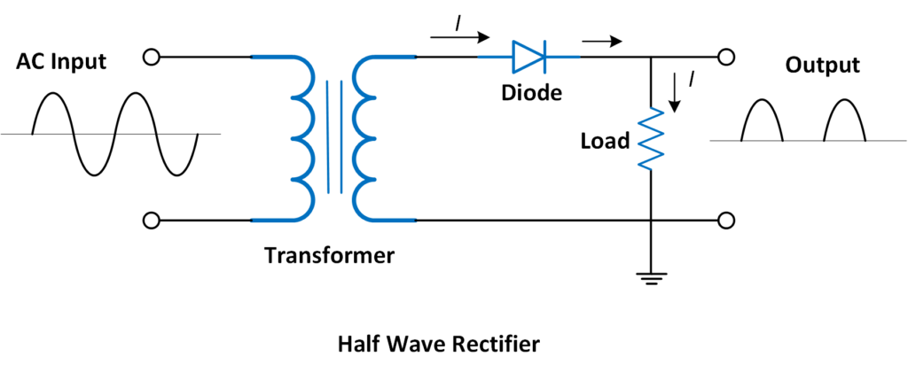
During the positive half-cycle of the AC input, the diode is forward-biased and conducts current (I), allowing it to pass through to the load. During the negative half-cycle, the diode is reverse-biased and blocks current, preventing it from reaching the load. This results in a pulsating DC output.
In a full-wave rectifier circuit, four diodes are arranged in a bridge configuration.
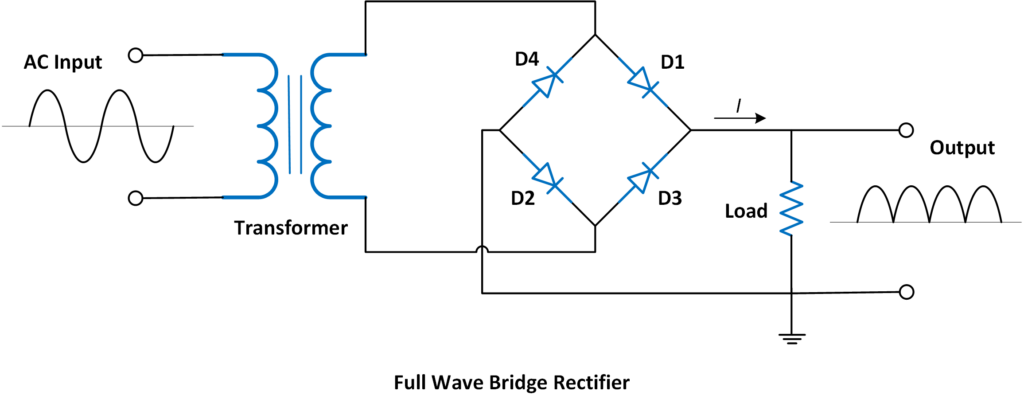
During both the positive and negative half-cycles of the AC input, different pairs of diodes (D1 & conduct, ensuring that the current (I) flows in the same direction through the load. This configuration provides a smoother DC output compared to the half-wave rectifier.
Creator and Editor at AnitoCircuits.com based in Toronto
