A multimeter is a device specifically designed to measure the voltage drop, resistance, and amperage of electrical current in a circuit.
Although an oscilloscope can be used to measure these parameters, its primary function is to visualize and analyze the waveform of electrical signals over time. We frequently use oscilloscopes to capture the behavior of an AC voltage and current or AC signal in general.
But if you are dealing with basic circuits or DC circuits, you can just use a multimeter.
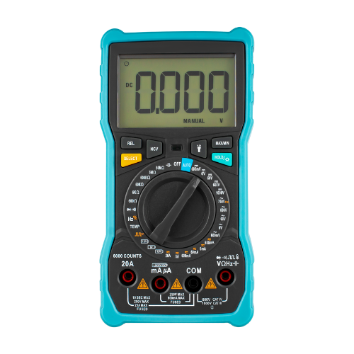
However, it’s important to note that multimeters come in various types, including digital and analog, and may have different ranges. So you have to set your multimeter with a range that includes the expected values within your circuit.
Additionally, you should also know the type of current or voltage you are measuring. Set the mode of your ammeter or voltmeter to measure either DC or AC. But in this discussion, we will mainly focus on DC circuits.
How to Measure Current in a Circuit
To measure how much current flows through a component or circuit, you need to set your multimeter to operate as an ammeter.
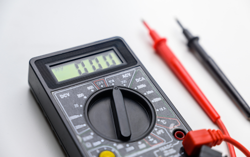
Turn the multimeter dial to the current setting (usually denoted by “A” for amperes or “mA” for milliamperes). Ensure you choose the appropriate range based on the expected current to be measured. For example, if you expect the current to be in the milliampere range, select the mA setting.
ⓘ Note
Always select a range that is higher than the expected current to be measured to prevent blowing the fuse inside the multimeter.
The ammeter should be connected in series with the component or section of the circuit you want to measure. Remember that the current that flows through it must also flow through the ammeter to complete a closed loop, otherwise, you will not get a reading.
For example, let’s take a look at the circuit below. If you want to measure the current (I2) that flows through the resistor R2, you have to place the ammeter in series right before or after R2.
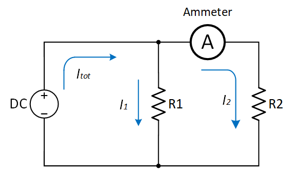
The ammeter has very low resistance, ideally approaching zero ohms (0Ω). Therefore, the presence of it does not significantly affect the overall resistance of the circuit.
How to Measure Voltage in a Circuit
To measure the voltage across a particular component, you also need to set your multimeter, but this time, to operate as a voltmeter.
To set it up, insert the black lead (common or negative) into the COM (common) socket on the multimeter and the red lead (positive) into the VΩmA (voltage, ohms, milliamps) socket. Make sure the leads are securely connected. Select the voltage function by turning the multimeter dial to the voltage (V) setting.
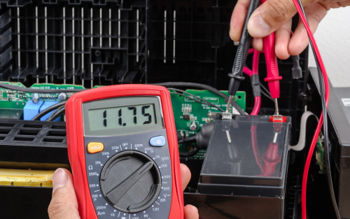
Note that a setting typically denoted by a V with a straight line or a series of dots above it indicates DC voltage. A V with a wavy line above or beside it indicates AC voltage. Choose the appropriate setting based on whether you are measuring DC or AC voltage. In this example, let’s assume we are working with a DC circuit.
Additionally, you need to set the voltage range higher than the expected voltage to be measured. For example, if you expect the voltage to be around 5 to 18 volts, you might want to start with the 20V range.
Place the voltmeter in parallel with the component or section of the circuit, as shown in the figure below. Ensure that the positive (+) lead of the voltmeter is connected to the point with higher potential and the negative (-) lead to the point with lower potential (ground or negative).
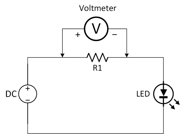
Read the voltage value displayed on the multimeter screen. If the voltage is within the selected range, it will display the voltage value directly.
Voltage Polarity
Please note that voltage can have polarity. This indicates the direction of the potential difference between two points in a circuit.
For example, let’s say you’re measuring the voltage drop across a resistor connected to a voltage source. In theory, the side connected to the higher voltage (positive terminal) is considered positive, while the side connected to the lower voltage (negative terminal or ground) is considered negative.
So, if you’re getting a positive voltage reading, it indicates that the positive lead of the voltmeter is connected to a higher potential than the negative lead. If you’re getting a negative voltage reading, it only means that the voltmeter is connected in the opposite polarity.
How to Measure Resistance in a Circuit
To measure electrical resistance, you have to set your multimeter to Ohmmeter. The ohmmeter is placed in parallel with the component. The meter’s direction does not matter because resistance has no polarity and can’t be negative in value.
First, you need to identify the specific component or section of the circuit from which you want to measure resistance. This could be a resistor, a section of a wire, or any other component with known or suspected resistance.
However, it’s important to consider factors such as parallel paths, interconnected components, and the presence of other circuit elements (such as capacitors or inductors) that can affect resistance readings.
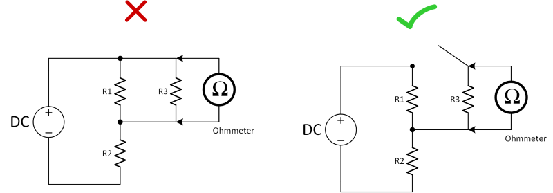
When measuring resistance across a single component, a resistor for example, in a circuit board with many interconnected components and paths, the reading may include resistance from other parts as well. Therefore, you must isolate and measure it separately from the entire circuit.
One way to do it is to lift or disconnect one lead of a resistor from the board, place the test probes across it, and take note of the resistance reading displayed on the ohmmeter/multimeter. This ensures that the resistance measured is only that of the resistor itself, without interference from other components.
But if you want to measure the total resistance of the circuit, you have to connect the ohmmeter directly across all the components.
Let’s take a look at the figure below, which shows a series-parallel circuit. The way to measure the total resistance is to disconnect the voltage source and replace it with the ohmmeter.
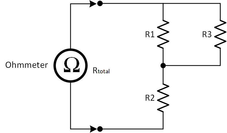
Keep in mind that the resistance you are measuring here represents the combined resistance of all components along every possible pathway between the test lead probes.
⚠ Caution
Do not connect the ohmmeter to a live circuit. Make sure to disconnect or turn off the power before measuring any resistance.
Creator and Editor at AnitoCircuits.com based in Toronto
