Description
This version of the LM386-based audio amplifier offers low noise, minimal distortion, and efficient power consumption. It operates within a 4V – 12V DC voltage supply and is capable of delivering a clean power output of 700mW.
The amplifier has a single channel, it outputs mono sound. However, it’s still sufficient and ideal for various audio systems and applications. It has features consisting of volume adjustment, gain control, and bass boost, all of which enhance the amplifier’s sound quality.
Additionally, it accommodates both wireless and wired input connections. A Bluetooth module and a 3.5 mm mini jack are integrated to facilitate the audio/music signals from phones, computers, etc. to be amplified and fed to its built-in speaker.
Having all that said, the amplifier comes equipped with an 8-ohm speaker and includes a dedicated 3D-printed box enclosure for efficiency and portability (see Figure 1).

Project Specifications
| Parameters/ Features | Description |
| Supply Voltage | 9V Recommended |
| Max Output Power | 700 mW |
| Circuit Impedance | 8 Ω |
| Features: | |
| Input Connection | 3.5-mm mini audio jack |
| Wireless | Bluetooth with distance connection of up to 20 meters |
| Volume Control | —db |
| Gain Control | 20 – 200 |
| Bass Boost | —db |
| Built-in Speaker | 8Ω Impedance, 30W |
| Case Housing | PLA Plastic |
| Switching Type | SPDT (non-illuminated) |
| Output Type | 1-Channel (Mono) |
| Amplifier Class Type | Class AB |
Project Applications
- Ideal as a Personal Portable Speaker System
- Desktop Speaker
- DIY Audio Projects
Circuit Design and Analysis
Schematic Diagram
Disclaimer: The audio amplifier circuit provided below is based on Scott Campbell’s circuit design from CircuitBasics.com.

Featured Op-Amp
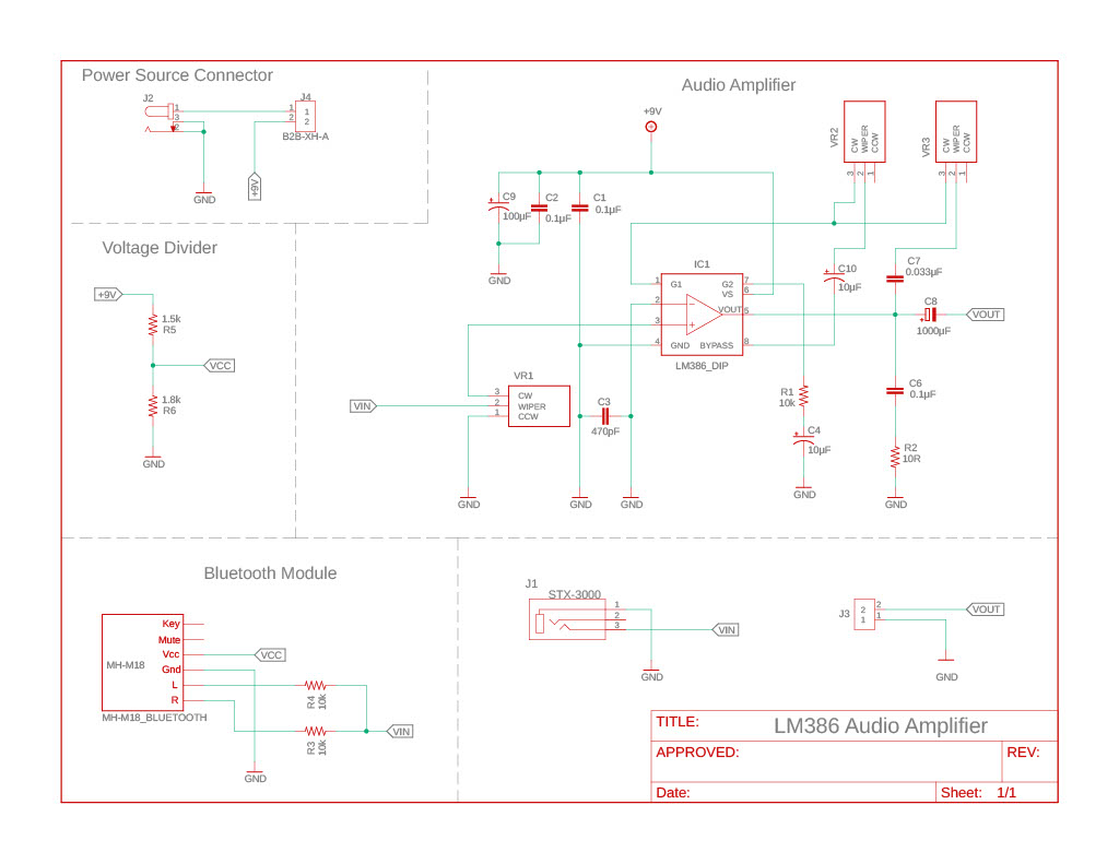
The amplifier uses the LM386 IC as the main driving component. It’s a versatile, low-voltage audio power amplifier chip widely used in electronics and audio applications. It is also ideal for battery operation and boosting small audio signals to drive a vast array of speakers.
| Recommended Operating Conditions | ||
| Parameters | Min | Max |
| VCC | 4 V 12 V | |
| VIN (Analog Input) | -4 V 4 V | |
| Speaker Impedance | 4 Ω 32 Ω | |
Decoupling capacitors
The LM386 is known for its sensitivity to interference and noise. So, a bunch of extra capacitors have been added to the circuit to at least reduce noise.
For example, 100 μF and 0.1 μF capacitors are connected between the positive and negative voltage supply rails to filter out high-frequency noise that is introduced from the power supply.
Gain Control
In the LM386 IC, two pins (1 and 8) are provided for gain control. We can use it to set the gain to any value from 20 to 200 by placing a 10 kΩ potentiometer in series with the 10 μF capacitor, as shown in the schematic diagram above.
Bass Boost
We can adjust the Bass sound of the amplifier by placing a series RC (10 kΩ and 0.033 μF) from pins 1 and 5. This filters out most of the noise that is not taken out by the decoupling capacitors. It also compensates for poor speaker bass response by frequency shaping the feedback path.
Bluetooth Connection
Besides the 3.5mm mini jack input connector, a Bluetooth module (MH-M18) that supports WAV and MP3 lossless decoding is integrated.
However, since the amplifier is mono, the stereo dual-channel output of the Bluetooth module is converted to a mono channel by connecting a resistor to each of the left and right outputs, as shown in the schematic above.
Other information on the module can be found on its datasheet.
Load Impedance (Speaker)
Another parameter considered in this project is the load (speaker) impedance. It should match the amplifier circuit’s impedance; therefore, I used an 8 Ohms general purpose speaker (30 W, 100 Hz ~ 20 kHz) to ensure the amplifier would not overheat and introduce distortion while delivering quality sound.
- Product Number: FRS 8 – 8 OHM
- Manufacturer: Visaton GmbH & Co. KG
- Speaker Datasheet
Based on the LM386 datasheet, the chip is designed to handle load impedances as low as 4 ohms; however, this will require more current to be delivered into it.
The speaker can be replaced with an impedance of 4 ohms up to 32 ohms; however, it’s still recommended to take the necessary precautions to avoid generating unnecessary heat within the circuit and prevent overloading the speaker.
PCB Design
The PCB layout, together with the schematic capture, is designed using Fusion 360 electronics workspace. The parameters and configurations are outlined below.

- Board Dimension & Outline: 2.9 inches x 1.8 inches, Rectangular
- Layer Count: Bottom Layer Only
- Trace Width and Spacing: 32 mills for all traces
- Component Mounting: Through Hole
- Material: FR4 Copper Board

Note that a copper pour is added to the ground layer to create a solid ground plane. This also helps reduce noise and improve the overall performance of the circuit.
Additionally, it’s important to align components for efficient assembly and soldering, typically following a grid pattern. Having that said, I have considered sufficient space between components for heat dissipation.
PCB Fabrication and Soldering
For this project, the Gerber files, extracted from the software, are forwarded to a PCB manufacturer or “PCB house.” I have opted for JLCPCB.com to manufacture the circuit board. I then assembled and soldered the components that I mostly procured at DigiKey.ca (see figure below).


Final Project Prototype
To complete the project prototype, we included an enclosure to make it look professional. This also makes the project more portable and efficient. This enclosure box is also designed with Fusion 360 based on the rendered PCB. Another reason for including a dedicated enclosure is to ensure good acoustics and minimize distortion.
Enclosure Box Specifications
| Parameters | Value | |
| Overall Dimension | 99.7 mm x 72 mm x 123.91 mm | |
| Wall Thickness | Main Body | 2 – 3.5 mm |
| Back Panel | 2 mm | |
| Fitting | Screw Type | |
| Weight | — g | |
| Material | Plastic PLA | |
| Manufacturing | 3D Printed | |
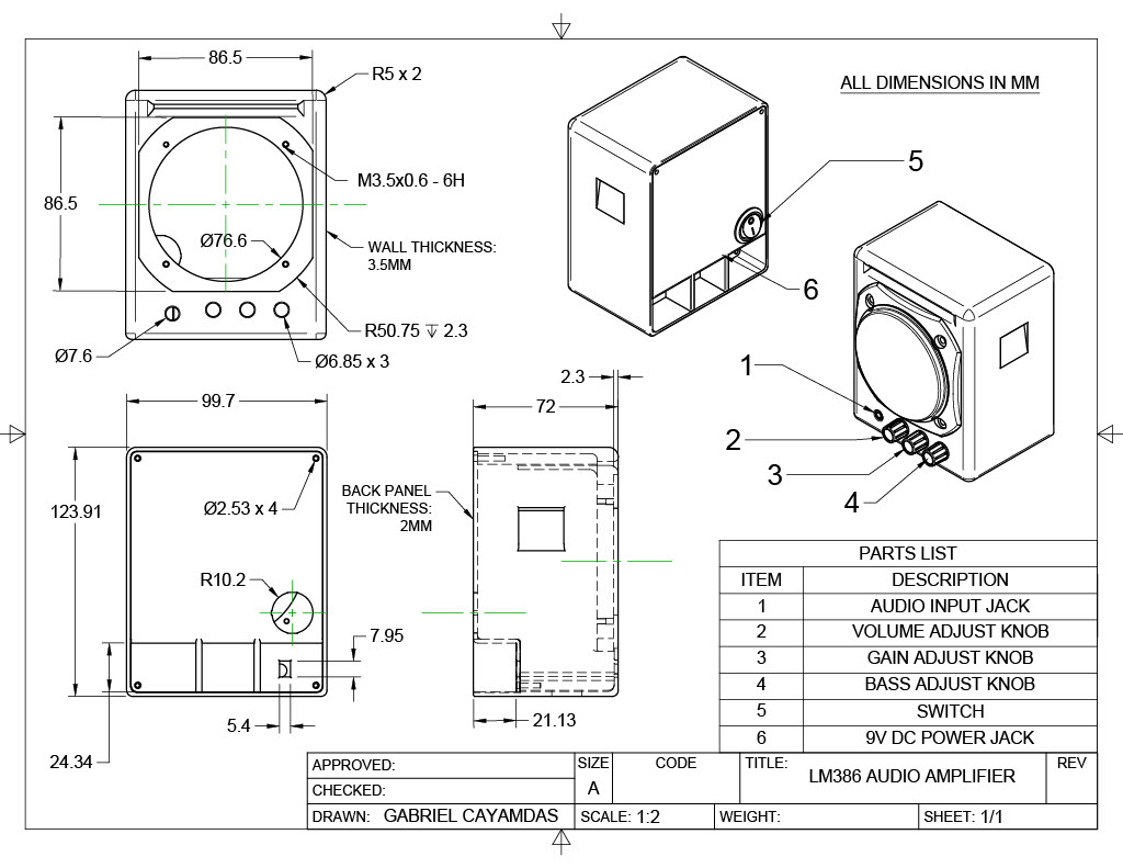
Drawing (Dimensions)

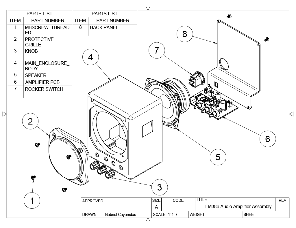
Parts Assembly

Bill of Materials
| QTY | PART NAME | DESCRIPTION | PRICE |
| 1 | IC1 | LM386_DIP | $1.65 |
| 1 | C7 | 0.033µF CAPACITOR | $0.225 |
| 3 | C1, C2, C6 | 0.1µF CAPACITOR | $0.675 |
| 1 | R5 | 1.5K RESISTOR | $0.079 |
| 1 | R6 | 1.8K RESISTOR | $0.079 |
| 1 | C8 | 1000µF CAPACITOR | $0.225 |
| 1 | C9 | 100µF CAPACITOR | $0.225 |
| 1 | R2 | 10R RESISTOR | $0.079 |
| 3 | R1, R3, R4 | 10K RESISTOR | $0.237 |
| 2 | C4, C10 | 10µF CAPACITOR | $0.45 |
| 1 | C3 | 470PF CAPACITOR | $0.225 |
| 3 | VR1, VR2, VR3 | 10KOHMS POTENTIOMETERS 9MM | $16.74 |
| 1 | J1 | PHONE AUDIO CONNECTOR 3.5MM | $1.11 |
| 1 | J2 | CONN PWR JACK 2.1X5.5MM | $2.66 |
| 2 | J3, J4 | XH CONNECTOR | $1.20 |
| 1 | SWITCH ROCKER SPST 10A 125V | $1.34 | |
| 1 | SPEAKER 8OHM 30W TOP PORT 82DB | $25.43 | |
| 1 | PROTECTIVE GRILLE | $12.42 |
Discussion of Results
The amplifier project was successful and met all of the project requirements. When it comes to its performance, the amplifier can produce a clean amplified audio signal when used within its optimal operating conditions. For example, when adjusted to low to moderate volume levels, it produces clean and acceptable audio quality.
In addition, the 700mW output of the circuit was also well-matched to the speaker’s capabilities, delivering good volume without overloading the system.
However, I noticed distortion at high volumes. When pushed to its maximum output, it introduces distortion which affects the sound quality. In addition, it also produces noticeable background noise or hiss when adjusted to higher gain settings. Lastly, the amplifier can’t be driven at excessively high levels for long periods as it introduces heat.
Further Recommendations
While some distortion is observed at higher volume levels, this is expected due to the design and power output limitations of the LM386. We can still keep the distortion within manageable levels by carefully adjusting the gain.
To ensure overall satisfactory audio performance and minimize noise and interference, consider a well-designed circuit layout. This means keeping signal paths as short as possible and ensuring good grounding practices. This may help reduce unwanted noise to a certain degree.
Another thing to consider is using high-quality resistors, capacitors, and other components. They may improve the overall audio quality by ensuring stable and consistent performance.
Creator and Editor at AnitoCircuits.com based in Toronto