Whether you’re adjusting the volume on a speaker, dimming a light, or varying the speed of a motor, one essential component often comes into play: the potentiometer. It is also known as a variable resistor. This component allows you to fine-tune parameters such as current and voltage in a circuit by adjusting the resistance.
What is a Potentiometer?
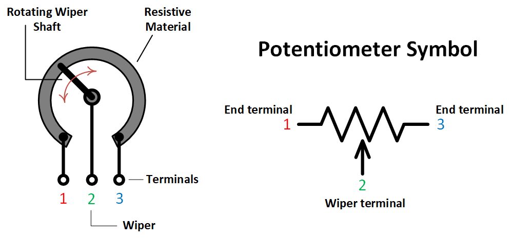
A potentiometer is a three-terminal resistor with an adjustable middle terminal (called a wiper), which allows you to change the resistance between two terminals.
Key Components of a Potentiometer:
- Two fixed terminals (1 and 3): These are connected to a resistive element.
- One adjustable terminal (Wiper): This is the movable part that slides along the resistive element, adjusting the ratio of resistances between terminals 1 – Wiper and Wiper – 3.
Current Flow and Resistance Adjustment
The current and voltage in a potentiometer circuit behave according to Ohm’s Law. For example, from the diagram below, let’s assume you are using terminals 1 and 2 in a simple circuit.
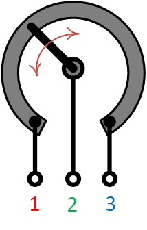
When you adjust the wiper’s position, you change the resistance in different parts of the circuit. This resistance change also regulates the current flowing through it, which directly affects the output voltage at the wiper.
- Low resistance occurs when you turn the wiper close to terminal 1, allowing more current flow, and raising the voltage drop across terminals 1 and 2.
- High resistance occurs when you turn the wiper close to terminal 3, restricting the current flow, and decreasing the voltage drop between terminals 1 and 2.
Potentiometer as a Voltage Divider
One of the most fundamental uses of a potentiometer is to act as a voltage divider. This principle is at the heart of how potentiometers work in many applications, especially when you need to create a variable reference voltage or control the voltage going to other components.
For example, let’s say you connect a 10kΩ potentiometer across a 9V power source.
- Turning the potentiometer fully to one side may give you 9V at the wiper.
- Turning it fully to the other side will give you 0V.
- Setting the potentiometer to the middle position would give approximately 4.5V at the wiper.
We can verify this, of course, by using a voltmeter or by calculation using the voltage divider formula.
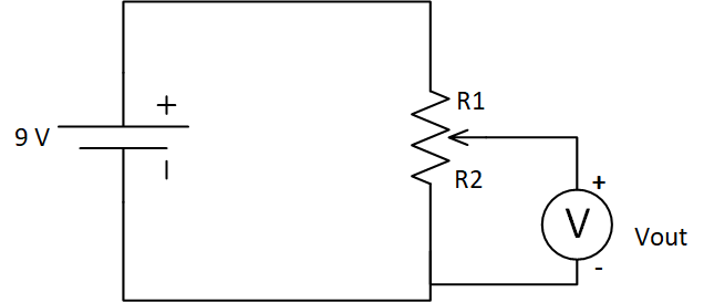
When the slider (wiper) of the potentiometer is in the middle, it divides the total resistance equally between R1 and R2. Since the total resistance of the potentiometer is 10kΩ, this makes R1 = 5kΩ and R2 = 5kΩ as well.
In this case, the output voltage (Vout) across R2 can be calculated using the voltage divider formula:
\[ V_{out} = V_{in} \times \frac{R_2}{R_1 + R_2} \]
\[ V_{out} = 9 \times \frac{5 \text{k}\Omega}{5 \text{k}\Omega + 5 \text{k}\Omega} = 4.5 \]
So, Vout is equal to 4.5 volts, which is half of the input voltage Vin.
Types of Potentiometers
There are several types of potentiometers, and sometimes each type is designed for different uses.
Rotary Potentiometer
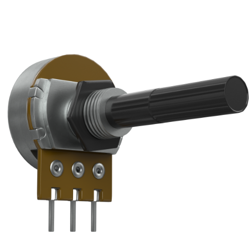
This is the most common type, featuring a knob/shaft that rotates to adjust the wiper’s position. You’ll find rotary potentiometers in devices like audio systems where they’re used to control volume.
Trimmer Potentiometer (Trimpot)
Trimmer potentiometers are small, and often used in situations where the adjustment is made once and then left in place, such as in tunning and calibration circuits. They’re typically fine-tuned with a screwdriver and mounted in circuit boards and electronic devices like radio transceivers.
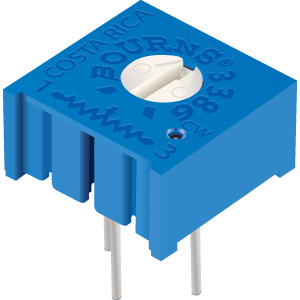
Linear Potentiometer
Instead of rotating, linear potentiometers use a slider that moves along a straight track. They’re often found in audio mixers, graphic equalizers, and sometimes lighting controls.
Applications of Potentiometers
Potentiometers are versatile and you can find them in many different types of electronic and electrical systems. Some of their most common applications include:
Volume Control
They are mostly used in audio systems to adjust or modify audio signals going to the speakers. For example, in my LM386 audio amplifier project, I used potentiometers to adjust not just the volume, but also the gain and bass boost of the amplifier.
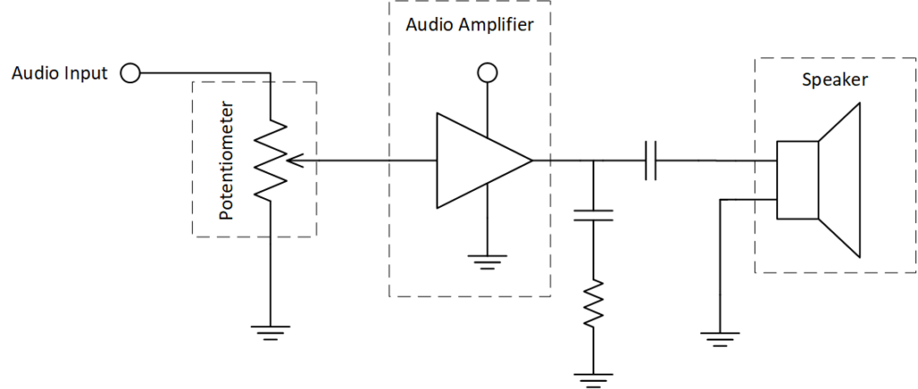
In the circuit above, volume control comes before the final amplification so that you can adjust the signal level that the amplifier receives. This way, the amplifier processes the modified signal strength (based on the volume setting) and sends that to the speakers.
Brightness Control
Potentiometers are often used in lighting systems to adjust the brightness of lights, including LEDs. It can be connected in series (see figure below) with a light source to vary the current, which directly affects how bright the light shines.
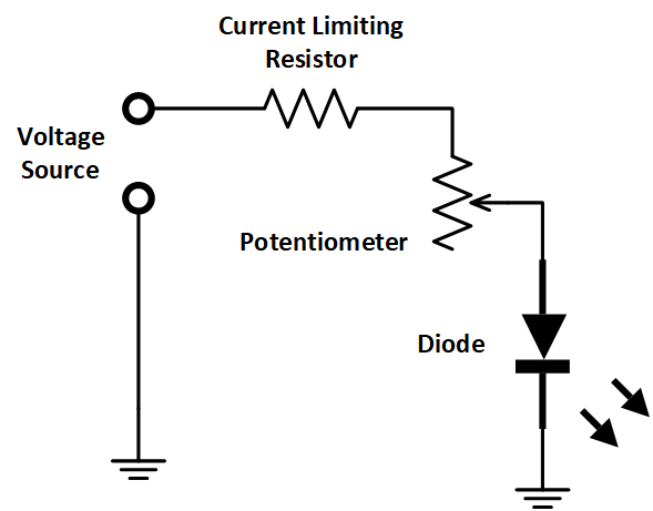
Here, a potentiometer is connected in series with an LED and a current-limiting resistor. By adjusting the potentiometer, the resistance changes, thereby controlling the current flow and adjusting the brightness of the LED.
Speed Control of DC Motors
In motor control systems, potentiometers help control the speed of DC motors. This comes in handy for stuff like fan controllers, motorized toys, etc.
By turning the potentiometer, you can increase or decrease the motor’s speed by changing the resistance, which adjusts the voltage applied to the motor.
What is the Difference Between a Potentiometer and a Rheostat?
While both potentiometers and rheostats are variable resistors, their primary functions and configurations in circuits differ significantly. For example, potentiometers are mainly used to control the voltage while rheostats are only to used to control the current. In addition, rheostats are generally more robust and better suited for high-current applications compared to potentiometers.
Can a Potentiometer be Used in Digital Circuits?
They are primarily used in analog circuits for continuous adjustments, but they can also be used in digital systems. For example, you can connect a potentiometer to an analog-to-digital converter (ADC), to provide variable input voltages that the ADC converts into digital signals. This is a common application in microcontrollers, where potentiometers are used to provide varying inputs for tasks such as adjusting screen brightness, adjusting fan speed and controlling a servo motor.
Creator and Editor at AnitoCircuits.com based in Toronto
