An inductor is an electronic component that quietly but strongly affects how devices work. Even though it’s less popular than capacitors and resistors, it plays a key role in energy control, noise suppression, and frequency tuning.

Introduction
The story of the inductor dates to the early 19th century, when British scientist Michael Faraday discovered the principle of electromagnetic induction. This groundbreaking realization (that a changing magnetic field could induce a voltage in a conductor) laid the foundation for how inductors, transformers, and even electric motors work today.
At first, inductors were simple wire coils used in early telegraphs and radios. They were fundamental building blocks in analog circuitry, crucial in tuning, filtering, and managing energy. While their function remained constant, their design and applications have expanded dramatically.
Today, manufacturers like Murata, Coilcraft, and Würth Elektronik continue to advance this legacy by offering a wide range of inductors tailored to modern demands, from RF circuits to high-efficiency power conversion.
See Also
- Explore the Difference Between Alternating and Direct Current.
What is an Inductor and How it Works
An inductor is a passive component that stores energy in a magnetic field when an electrical current passes through it.

Imagine a wire wound into a coil. As current flows, a magnetic field builds around it. When the current changes, the inductor resists that change by generating a voltage in the opposite direction—a property described by Faraday’s Law and Lenz’s Law.
Voltage across an inductor equals inductance times the rate of change of current.
This means inductors resist changes in current, making them ideal for smoothing out fluctuations and protecting circuits from voltage spikes.
Types of Inductors
Inductors come in several types, optimized for different functions:
- Air-core inductors: No magnetic core, ideal for high-frequency applications.
- Iron-core inductors: Used in low-frequency power supplies.
- Ferrite-core inductors: Popular in EMI suppression and high-efficiency power circuits.
- Multilayer chip inductors: Tiny, surface-mount components used in RF and mobile devices.
ⓘ Note
For high-Q RF designs, try Murata’s LQW series. Need compact power handling in your circuit projects? Go with Coilcraft’s XGL series.
To truly grasp the role of an inductor, it’s important to study it within actual circuits. The behavior of inductors becomes more meaningful when you see them in action.
RL Circuit
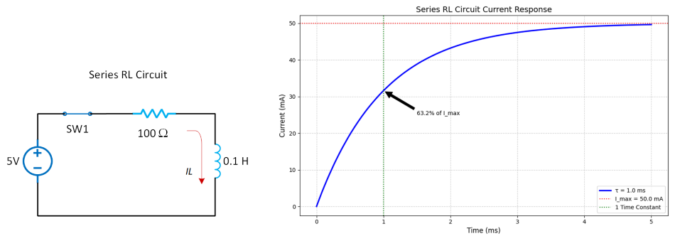
An RL circuit includes a resistor (R) and an inductor (L). Let’s take a look at the circuit below. When a DC voltage is applied, the current doesn’t immediately rise because the inductor resists change due to its magnetic field. Over time, the current gradually increases until it stabilizes, controlled by the time constant τ = L/R.
RL circuits help control the surge of current when devices are powered on. For example, in LED drivers, an RL network can limit inrush current and prevent thermal shock, also prolonging the LED’s lifespan.
Similarly, in power supplies, an RL stage introduces a gradual increase in current, acting like a soft start mechanism to protect sensitive loads. Würth Elektronik’s WE-PD series is often used here due to its excellent thermal and electrical characteristics in compact power designs.
Additionally, RL circuits are also used to delay signals (timing applications). It can be integrated into a circuit to introduce a delay that prevents false triggering or rapid switching due to noise.
Lastly, they are used to create simple low-pass filters to block high-frequency noise, like an RC circuit. Inductors resist high-frequency changes, so high frequencies are blocked or attenuated, while low frequencies pass.
Recommended Reading
- Learn more about Capacitor Charging: RC Time Constant.
- Explore what are Analog and Digital Signals.
RLC Circuit
An RLC circuit includes a resistor, an inductor, and a capacitor. It forms the basis of resonant circuits and is widely used in signal processing, audio electronics, and radio communications.
There are two common configurations, series RLC circuit and parallel RLC circuit.
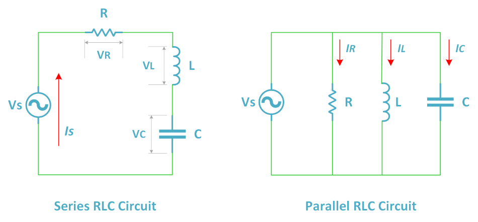
The series RLC Circuit offers a peak response at the resonance frequency, where inductive and capacitive reactance cancel each other out. This makes it ideal for band-pass filters, oscillators, or frequency selectors.
A parallel RLC Circuit, on the other hand, can act as a band-stop filter, rejecting a narrow frequency range, or serve in impedance matching networks in RF amplifiers.
In both cases, the inductor works with the capacitor to either reinforce or suppress certain frequencies.
With that being said, they are mostly used in radio tuners, where the circuit isolates and amplifies a specific station’s frequency while filtering out others. Coilcraft’s MLR inductors are favored for these applications due to their high Q factor, which provides sharp frequency selectivity and minimal energy loss.
Natural Frequency (f₀)
The frequency at which the system resonates.
Q Factor (Quality Factor)
It represents how underdamped an oscillator is and relates to the sharpness of the resonance.
Higher Q means a sharper and more selective resonance, useful in filters and tuned amplifiers.
Damping
Introduced by the resistor. A low resistance leads to sustained oscillation (underdamped), while a higher resistance leads to overdamping and energy dissipation.
Inductors in Power Electronics: Buck, Boost, and Beyond
Inductors act as energy reservoirs in switching regulators like buck (step-down) or boost (step-up) converters.

During the “on” cycle, a transistor conducts current through the inductor, building up a magnetic field and storing energy. When the switch turns “off”, the inductor’s magnetic field collapses and releases the stored energy, maintaining current flow to the load and smoothing the output.
This switching action, when properly timed and controlled by a PWM controller, allows for highly efficient DC-DC conversion, often exceeding 90% efficiency. Without inductors to store and transfer energy between cycles, such efficiency and compact design would be impossible.
Modules like Texas Instruments’ TPSM53604 already integrate power inductors with regulators, improving efficiency and reducing board complexity. Similarly, Analog Devices’ Silent Switcher™ technology uses embedded inductors to significantly cut EMI, crucial in automotive and industrial systems.
Inductors are important for blocking electromagnetic interference (EMI) and protecting devices from sudden voltage spikes. They help keep power supplies stable and signals clean, especially in sensitive analog and RF circuits. For example, TDK’s SPM and MLG series inductors are commonly used in mobile devices to control EMI. By blocking high-frequency noise, inductors help prevent nearby circuits from being disrupted and protect the overall system.
Next Steps
- Learn more about the Basic Electronic Components in Circuits.
- What is a Potentiometer and Variable Resistor?
- Explore what a Bipolar Junction Transistor (BJT) is.
Creator and Editor at AnitoCircuits.com based in Toronto