Op-amp comparators are circuits that use an operational amplifier (op-amp) in an open-loop configuration (without negative feedback) to compare two input voltages. The op-amp’s output rapidly saturates to either the positive or negative supply rail, depending on which input voltage is larger. Due to this binary output behavior, an op-amp comparator functions as a basic analog-to-digital converter.
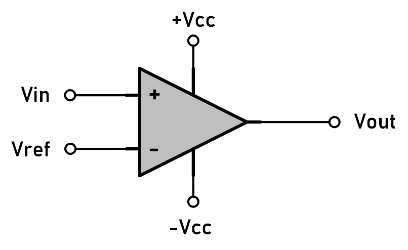
Op-amp Comparator Configuration
A common comparator circuit is built by configuring an operational amplifier in an open-loop (no feedback) configuration. The op-amp has two inputs:
- Non-inverting terminal (+): Receives the signal (Vin) that will be compared.
- Inverting terminal (-): Typically set to a reference voltage (Vref) to establish the threshold.
Please note that the op-amp has no feedback path in an open-loop configuration, meaning its gain is extremely high. Even the smallest difference between the inputs is amplified until the output reaches its maximum or minimum supply voltage.
Non-inverting Op-amp Comparator
A non-inverting op-amp comparator, often referred to as a positive comparator, produces a HIGH output when the voltage at the non-inverting (+) input is higher than the voltage at the inverting (-) input. In this configuration, the reference voltage (Vref) is typically connected to the inverting terminal, while the input signal (Vin) is connected to the non-inverting terminal.
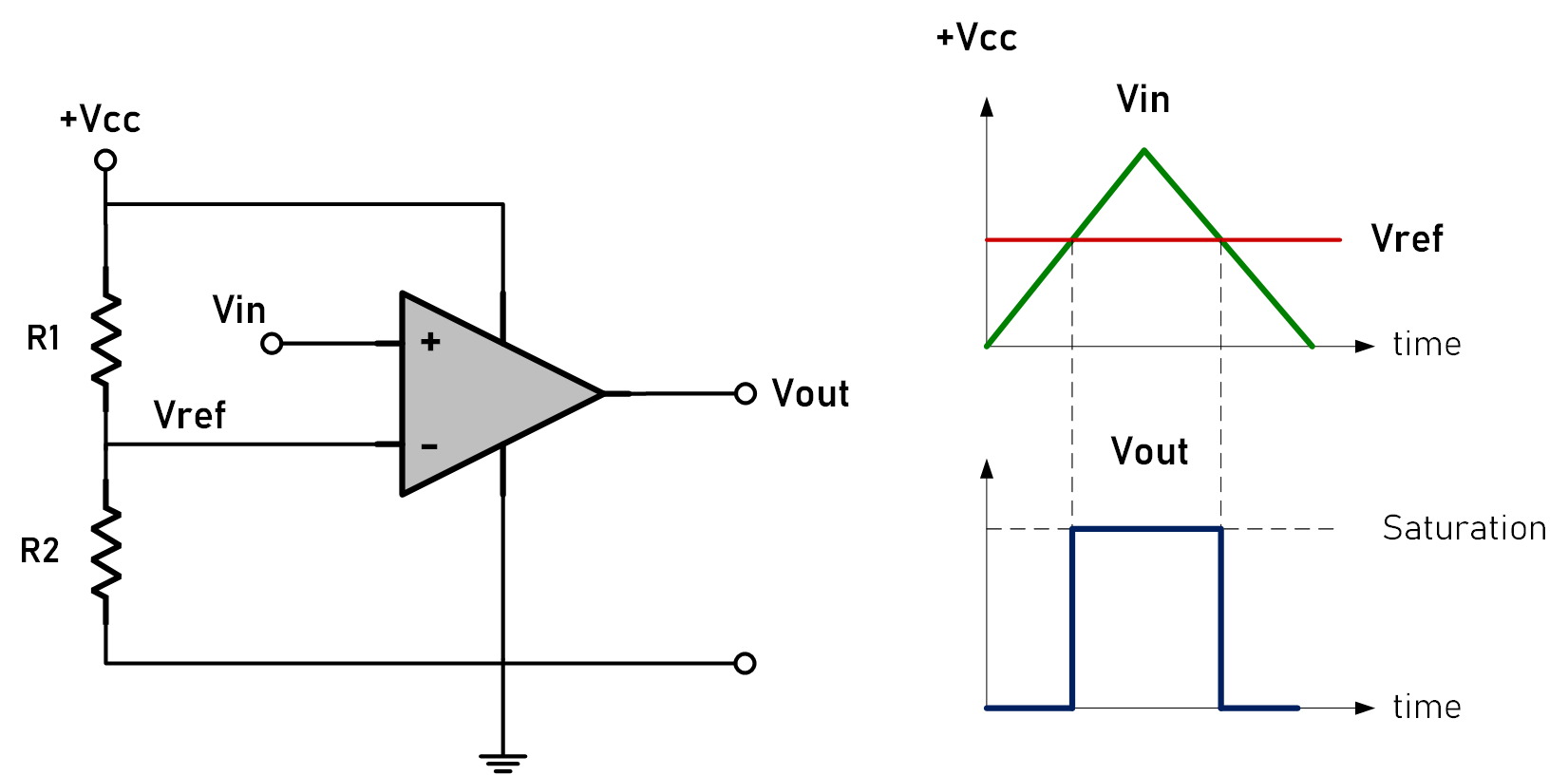
Let’s take a look at the circuit above. The output voltage (Vout) saturates to the positive supply rail (+VCC) when the input voltage (Vin) exceeds the reference voltage (Vref). When Vin drops below Vref, the output in the circuit switches to 0V because the op-amp is powered by a single power supply.
For instance, if the reference voltage is set at 2V, the comparator will output a high signal when the input voltage at the non-inverting terminal exceeds 2V.
Additionally, this behavior makes the op-amp act as a binary device: its output is either fully on or fully off, perfect for comparing voltage levels without needing an analog output.
Inverting Op-amp Comparator
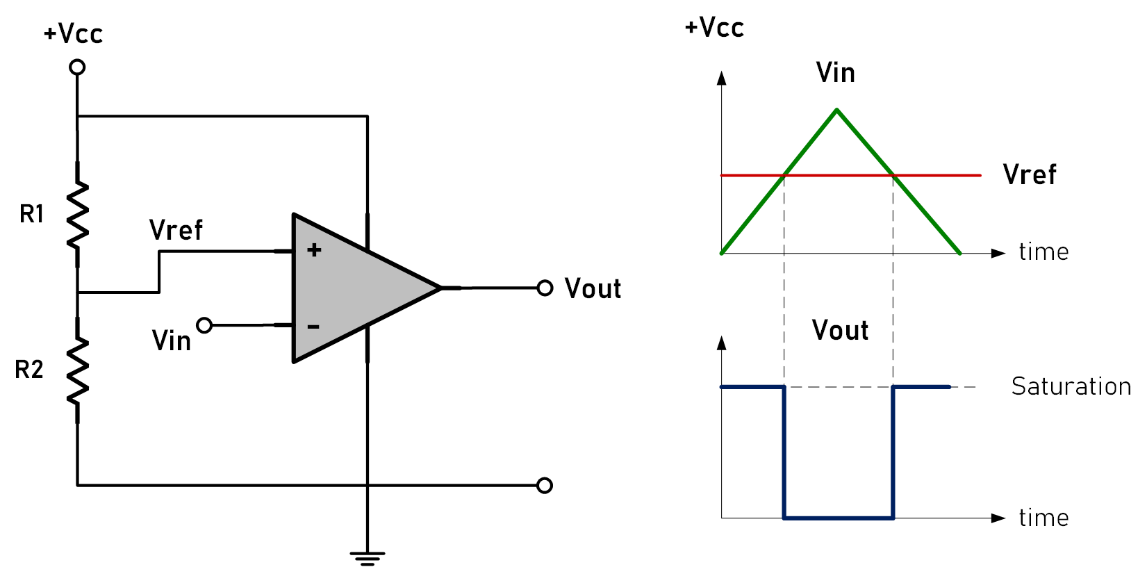
An inverting op-amp comparator, or negative comparator, behaves similarly but with opposite inputs. The reference voltage Vref is applied to the non-inverting input, while Vin is connected to the inverting input.
When Vin is higher than Vref, the output switches to the negative supply rail (−VCC), but in the circuit below, the output switches to 0V, since the op-amp is powered with a single power supply. When Vin falls below Vref, the output goes HIGH, saturating towards the positive supply rail (+VCC).
See Also:
- Learn more about Non-Inverting Operational Amplifier (Op-amp) Circuits.
- Explore Inverting Operational Amplifier (Inverting Op amp).
Practical Considerations for Comparator Circuits
Setting a Reference Voltage
One of the inputs, often the inverting terminal, is connected to a fixed reference voltage. This voltage sets the threshold level.
Now, a common configuration is a circuit with a fixed voltage divider reference source. The junction point between R1 and R2 provides the reference voltage (Vref).
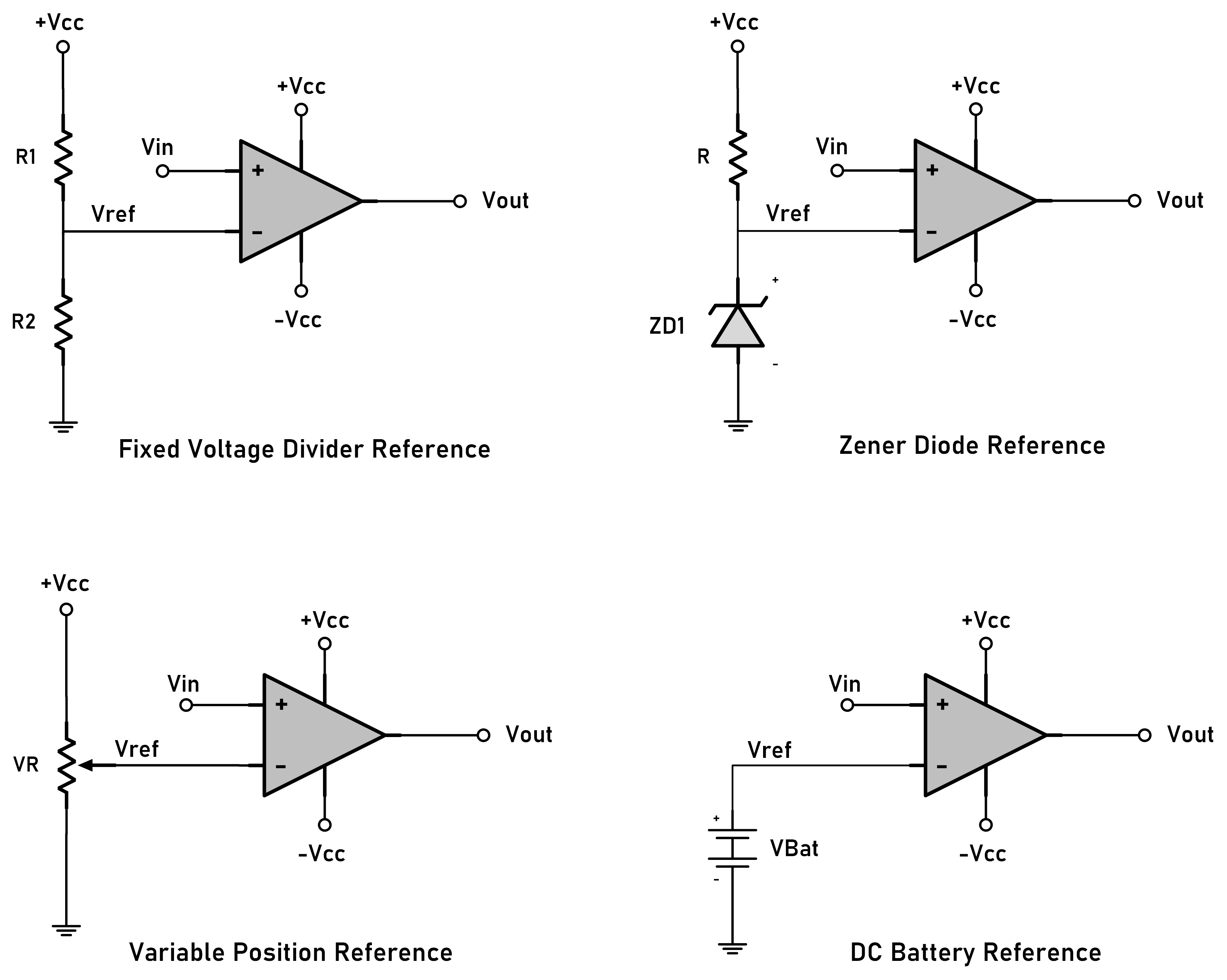
However, please note that there are several ways to configure the voltage reference source in an op-amp comparator, depending on the requirements of your circuit. For example, you can use an adjustable voltage divider with a potentiometer, Zener diode reference, etc.
Hysteresis and Noise Margin
It’s important to note that open-loop comparators can be susceptible to noise and oscillations, especially with slowly changing input signals. To prevent unwanted oscillations due to noise or slow-changing input signals, positive feedback is used to create hysteresis in the comparator circuit. This configuration is also called a “Schmitt Trigger.”
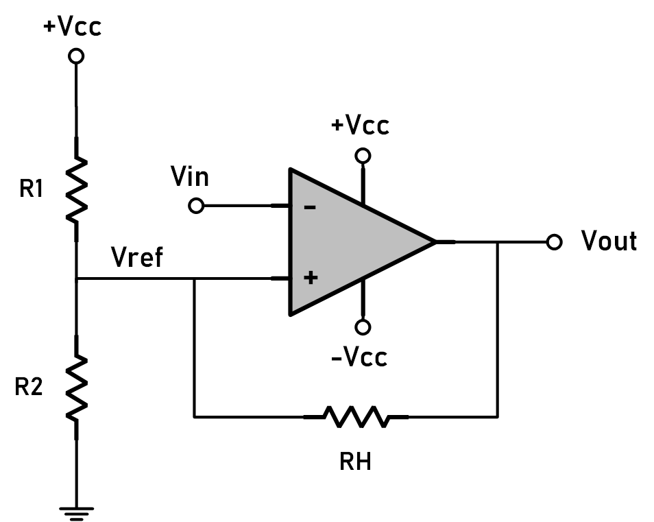
Hysteresis is achieved by adding a small amount of positive feedback, creating a slight difference between the high and low switching points. This improves stability by preventing erratic output behavior.
Power Supply and Output Limits
Op-amp comparators are limited by their power supply. The output voltage can only swing as high or as low as the supply voltages allow, so “rail-to-rail” comparators may be necessary for low-voltage digital systems.
Consider the power supply requirements and limitations of your circuit when choosing an op-amp for a comparator application.
Op-amps Vs Dedicated Comparators
While op-amps can be used as comparators, dedicated comparator ICs, like the LM311, LM339, and LM393, are optimized for fast switching and saturation, offering better performance. They have specialized output stages designed for continuous saturation and tend to have lower power consumption compared to op-amps used as comparators.
Applications of Comparators
Voltage Level Detector
A comparator can monitor voltage levels to detect when they exceed or fall below a set value. For example, it might monitor battery levels and trigger an alert when the voltage falls below a certain threshold, signaling the need for recharging.
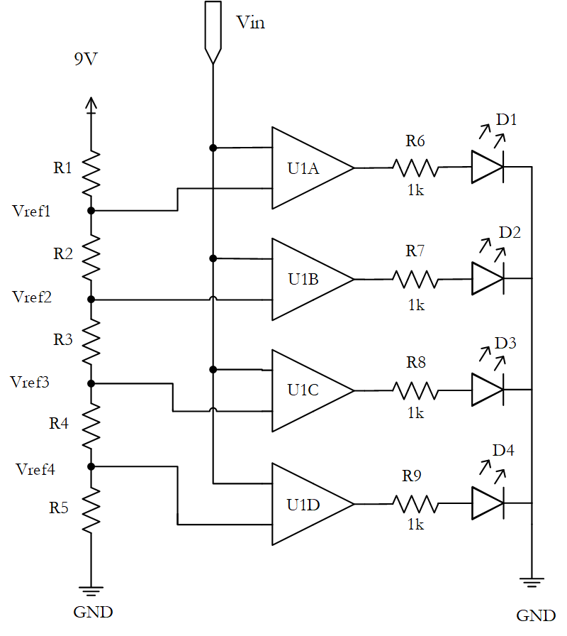
Take a look at this LED bar graph meter circuit project, which operates based on comparator principles.
Analog to Digital Converter (ADC)
Consider a voltage-level detector circuit using multiple op-amp comparators. If eight comparators are connected in a chain, with each comparator having a distinct reference voltage, and the output of each comparator feeds into an 8-to-3 line digital encoder, this setup can function as a basic ADC.
Zero-Crossing Detector
A window comparator circuit can be used as a zero-crossing detector for a sinusoidal waveform. By setting the upper and lower trip levels to specific voltages, for example, ±10 volts, the circuit produces a HIGH or LOW output each time the sine wave crosses zero volts. This feature is also useful for applications such as phase-locked loops and sine-to-square wave converters.
Pulse Width Modulation (PWM) Generation
PWM signals can be generated by comparing a sawtooth waveform to a control voltage. When the control voltage is higher than the sawtooth waveform, the comparator outputs a high signal, and when it’s lower, the output is low, creating a PWM signal used in motor controls and LED dimming.
Temperature Control
A comparator with a temperature sensor can be used to control a heater. When the temperature drops below a predetermined level, the comparator’s reference voltage triggers the heater to turn on. Adding hysteresis to this circuit is recommended to prevent rapid on-off cycling of the heater.
Comparator in Digital Circuits
In digital systems, comparators play an essential role in simplifying complex circuits by reducing analog signals to binary outputs. Let’s explore some common digital applications.
1. Threshold Detection
Comparators detect when an input signal crosses a certain level, or “threshold.” This function is widely used in control systems, sensors, and logic gates. For instance, in a temperature control system, a comparator can monitor whether the temperature exceeds a certain threshold, activating cooling or heating systems accordingly.
2. Binary Output (Digital Signal)
The comparator operates as a two-state device, providing a high or low output based on the input conditions. This binary nature makes comparators perfect for digital circuits that require simple on/off signals.
By setting a reference voltage at one input, the comparator can define a cutoff point, switching its output whenever the input signal crosses this threshold.
3. Signal Conditioning
Comparators are frequently used to convert analog signals to digital pulses. This conditioning allows analog signals to be processed by digital systems, such as microcontrollers or digital logic circuits, improving integration between analog sensors and digital processors.
Next Steps:
- Explore the Current, Voltage, and Resistance Relationship.
- Learn more about Field-Effect Transistors (FETs).
Creator and Editor at AnitoCircuits.com based in Toronto