The primary function of an operational amplifier (op-amp) is to amplify voltage signals, and it accomplishes this through a combination of distinctive features.
Picture the op-amp as a highly efficient amplifier with two entrances: the inverting and non-inverting inputs. These inputs play distinct roles in shaping the output signal.
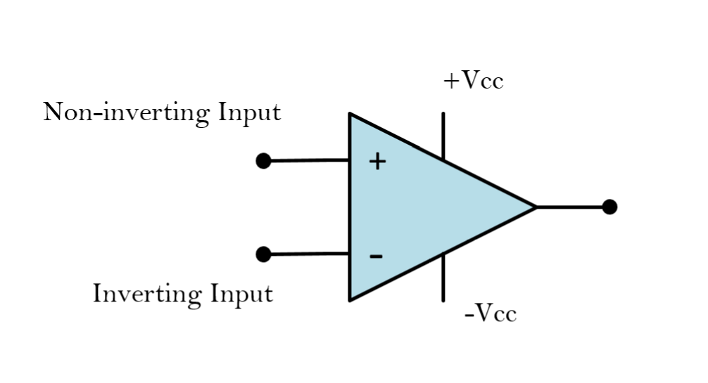
The op-amp’s ability to significantly boost the strength of a signal is attributed to its high input impedance, meaning it doesn’t draw much current from the source, and its low output impedance allows it to drive loads without significant signal loss.
In the context of an inverting operational amplifier, this is a specific configuration of an op-amp designed to generate an output voltage that is opposite in direction to its input voltage.
See also
- Learn more about the Non-inverting Op-amp.
What is an Inverting Op-amp?
The inverting operational amplifier is like a magic mirror for signals. It takes an input signal, flips it upside down, and magnifies it. This operation is achieved through a negative feedback connection.
Negative feedback is the key feature in this inverting amplifier configuration to produce a closed-loop operation. It plays a crucial role in stabilizing the circuit, controlling gain, and improving overall performance. It ensures that the op-amp operates in a linear and controlled manner.
In cases of negative gain, a positive input voltage results in a corresponding negative output voltage, and conversely, a negative input voltage leads to a positive output voltage.
Inverting Op-amp Circuit Configuration
The circuit configuration below shows that the input signal is connected to the inverting (-) input. Negative feedback is provided through a resistor (Rf) connected from the output to the inverting input. The non-inverting (+) input is connected to the ground.
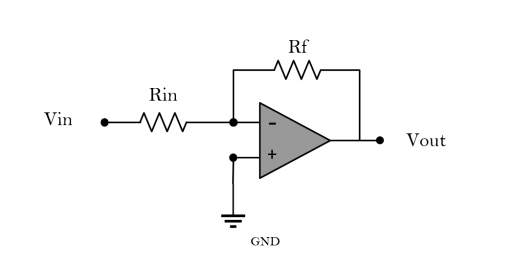
A resistor (Rin) is connected to the inverting (-) input of the op-amp and serves as the resistor through which the input signal flows. Its primary purpose is to set the input impedance of the circuit. This will control how much the circuit loads or draws current from the source providing the input signal.
Having a higher Rin value will result in a higher input impedance. This is beneficial for preventing excessive source loading and maintaining signal integrity.
On the other hand, a feedback resistor (Rf) is connected from the output of the op-amp to the inverting (-) input, creating a negative feedback loop. Its purpose is to determine the amount of feedback applied to the circuit. This will also influence the overall gain of the operational amplifier circuit.
Recommended Readings
- Explore Resistors in Series and Parallel.
- Learn more about Voltage, Current, and Resistance.
Inverting op-amp Gain
The gain of an inverting amplifier is determined by the ratio of resistors in the feedback and input networks of the op-amp circuit. Since the output is 180 degrees out of phase with the input, the gain is expressed as a negative value, reflecting the signal inversion inherent to this configuration.
In an inverting amplifier circuit, the non-inverting terminal of the operational amplifier (op-amp) is connected to ground, which influences the voltage at the inverting terminal. This behavior follows key principles governing op-amps:
- Voltage Rule: The op-amp strives to maintain a virtually zero voltage difference between its inputs (i.e., V1−V2=0), also known as the virtual ground at the inverting terminal.
- Current Rule: No current flows into the op-amp’s input terminals, as they present extremely high input impedance.
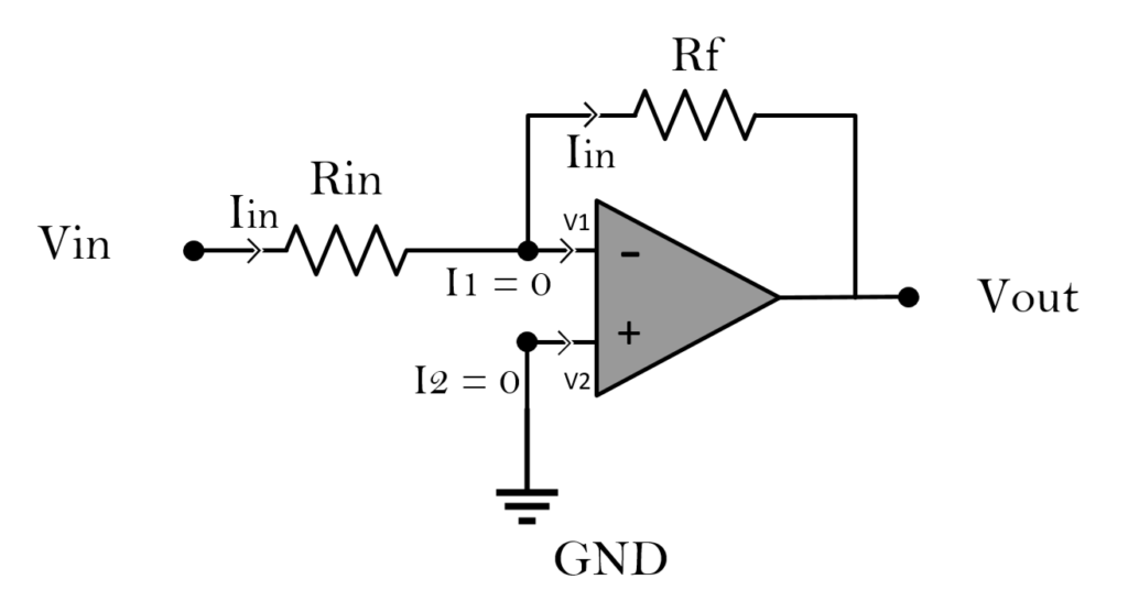
In the circuit, the input voltage (Vin) is applied to the inverting (-) input of the op-amp. The feedback resistor (Rf) is connected from the output of the op-amp to the inverting input. This creates a negative feedback loop, influencing the inverting input voltage.
So, the current (Iin) entering the inverting terminal is determined by the input voltage (Vin) and the input resistor (Rin).
\[ I_{in} = \frac{V_{in}}{R_{in}} \]The same current (Iin) also flows through the feedback resistor (Rf) due to the virtual short circuit principle.
Based on ohms law, this makes the output voltage (Vout) the product of the current (Iin) and the feedback resistor (Rf):
\[ V_{out} = -IR_f = -\frac{V_{in}R_f}{R_{in}} \]Substituting the expression for Iin from the equation above into the output voltage equation, the gain is derived as:
\[ \text{Gain} = -\frac{R_f}{R_{in}} \]Inverting and Amplifying an Input Signal
The inverting op-amp configuration offers a convenient method for incorporating negative feedback. But we can also use the inverting op amp to amplify and invert an input AC signal.
Suppose my input is a sinusoidal signal, an inverting operational amplifier will generate a waveform mirrored and amplified across the horizontal axis as shown in the figure below.

When working with sinusoidal signals, the negative gain of an inverting amplifier indicates that the output is 180 degrees out of phase with the input. This phase inversion occurs because the inverting op-amp configuration produces an output voltage that moves in the opposite direction to changes in the input voltage, resulting in a complete phase shift.
Additionally, the ratio of Rf to Rin determines the gain of the amplifier according to the formula. Adjusting Rf allows for control over the amplification factor.
- Increasing the value of Rf or decreasing the value of Rin will result in a higher gain.
- Decreasing the value of Rf or increasing the value of Rin will result in a lower gain.
After adjusting the resistor values, recalculate the gain using the formula. You must keep the ratio -Rin/Rf consistent with your desired gain. For example, if you want a gain of -3, ensure that \(R_f/R_{in} =3.\)
Lastly, depending on the configuration, such as using multiple resistors or variable resistors, adjust them accordingly to achieve the desired amplification.
Inverting Op amps Applications
- Cancellation of Undesired Signals: In certain applications, inverting a signal helps cancel out undesired components or interference. This is particularly crucial in communication systems and audio processing where unwanted noise or phase issues need mitigation.
- Phase Compensation: Signal inversion is also essential for phase compensation in circuits. In applications like feedback systems and audio processing, precise control over the phase relationship between input and output signals is critical for optimal performance.
- DC Offset Removal: Inverting amplifiers are utilized to remove DC offset in signals. This is beneficial in applications where an accurate representation of the AC component of a signal is required without the interference of a constant DC bias.
- Enhanced Flexibility in Circuit Design: The ability to invert signals provides engineers with enhanced flexibility in circuit design. It allows for the creation of circuits with specific characteristics, facilitating customization based on the requirements of a given application.
Advantages of Inverting Op amps
- Precision and Predictability
- Stability with Negative Feedback
- Common-Mode Rejection
- Versatility in Signal Processing
- Ease of Implementation
Limitations of Inverting Op amps
- It may have a limited output voltage swing, especially when powered from a single supply.
- Inverting amplifiers can be sensitive to noise, and careful consideration of resistor values, circuit layout, and grounding is necessary.
- In multi-stage designs, the use of inverting amplifiers might introduce complexity in managing signal phase relationships.
- While the input impedance of the inverting amplifier is determined by the input resistor, the choice of this resistor can impact the interaction with the source.
FAQs
Q: Can an inverting amplifier be used for DC signals?
A: Yes, inverting amplifiers are suitable for both AC and DC signals. While often associated with AC signal processing, they can effectively amplify and invert DC signals, making them versatile for various applications, including DC offset removal.
Q: Can an inverting amplifier be designed for variable gain?
A: Yes, inverting amplifiers can be designed for variable gain by using a variable resistor (potentiometer) as the feedback resistor (Rf). This allows for real-time adjustment of the gain based on specific application requirements.
Q: Are there specific considerations when cascading multiple inverting amplifiers in a circuit?
A: When cascading multiple inverting amplifiers, careful consideration is needed to manage signal phase relationships. The cumulative effect of phase inversions must be accounted for to ensure the overall system behaves as intended. Proper design and understanding of the signal flow are essential in multi-stage configurations.
Next Steps
- Learn more about Capacitors.
- Explore Bipolar Junction Transistors (BJTs).
Creator and Editor at AnitoCircuits.com based in Toronto