Operational amplifiers (Op-Amps) are integral electronic components with various applications, including mathematical operations such as addition, subtraction, integration, and differentiation. They are characterized by their linear behavior and nearly ideal DC amplification properties, making them essential for signal processing and control systems.
What is a Non-Inverting Op Amp
A non-inverting amplifier is an op-amp configuration where the input signal is applied to the non-inverting terminal, resulting in an output signal that is in phase with the input, as shown in the figure below.
The output signal is not phase-inverted relative to the input. Instead, it is amplified with the same polarity as the input, resulting in a positive gain.
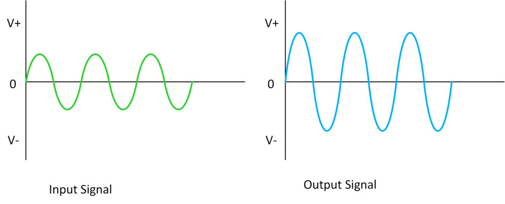
Now, non-inverting amplifiers are crucial in signal processing systems, where amplifying the signal without changing its polarity is essential. They are commonly used when high input impedance is necessary, which also makes them ideal for buffering applications.
Circuit Diagram and Configuration
The figure below shows a non-inverting amplifier configuration that consists of an op-amp and two resistors (one for feedback and one for grounding the inverting input).
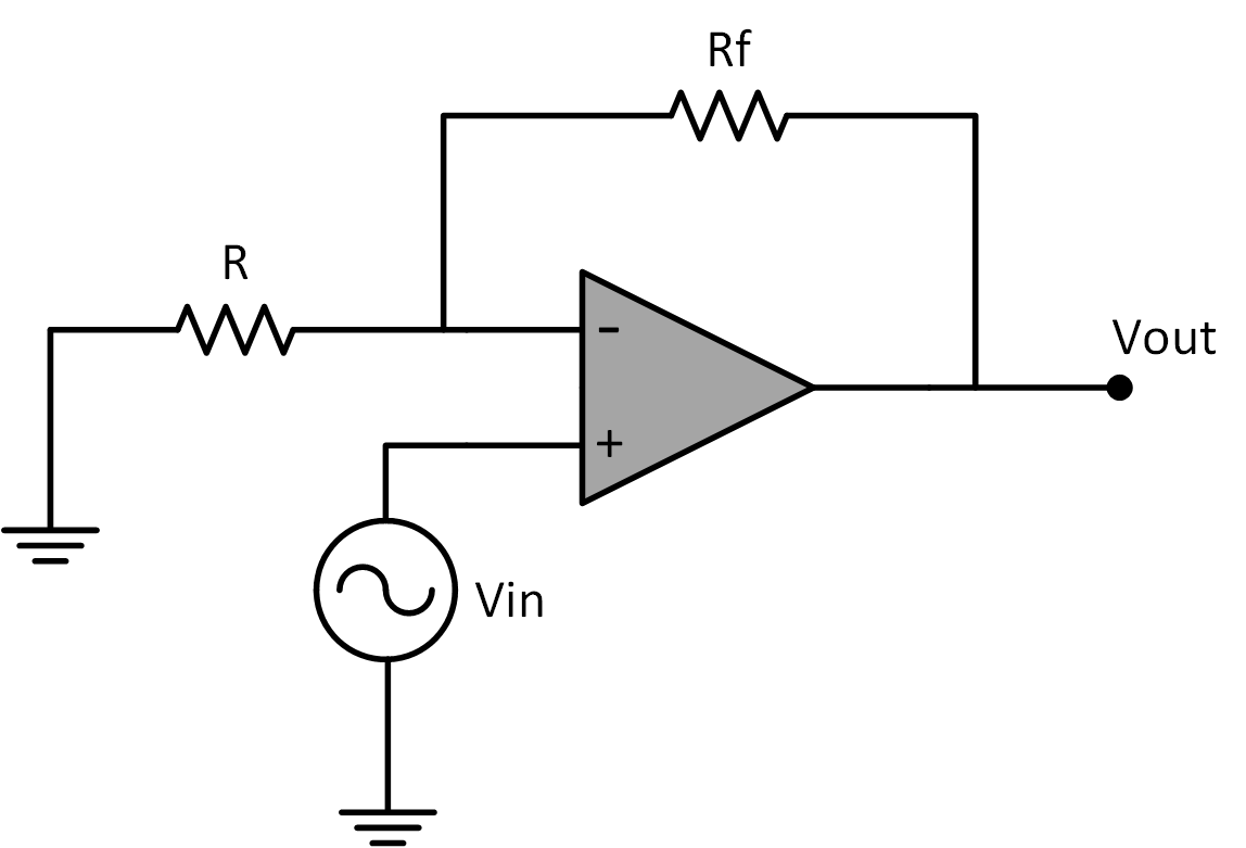
Notice in this circuit that the non-inverting terminal (+) is where the input signal is applied. The inverting terminal (-) is also connected to the output through a feedback resistor (Rf), and to the ground through a resistor (R).
Again, when the input signal is applied to the non-inverting terminal of the op-amp, that signal is then amplified with no phase inversion. The gain of the circuit determines how much the input is amplified.
In this case, it’s important to remember that the feedback loop regulates the gain and output voltage.
Voltage Gain Formula
The voltage gain (Av) of a non-inverting op-amp is given by the formula:
\[A_v = 1 + \frac{R_f}{R}\]
Rf is the feedback resistor and R is the resistor connected to the ground. Note that the gain is primarily set by the ratio of the resistances Rf and R, with an additional constant factor of 1 that accounts for the non-inverting configuration.
Example
Given a feedback resistor Rf=9.1kΩ and a resistor R=1kΩ, the voltage gain can be calculated as:
\[A_v = 1 + \frac{R_f}{R} = 1 + \frac{9.1k}{1k} = 10 .1\approx 10 \]
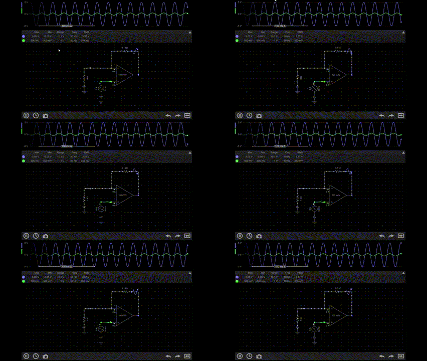
This means the output voltage will be ten times the input voltage. Let’s simulate it in a circuit and let’s see the waveforms.
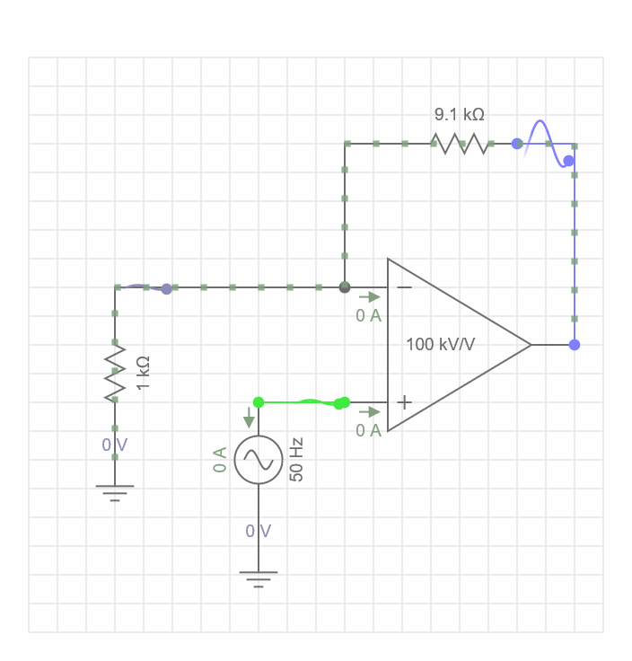
From the circuit above, the input signal has an amplitude of 500 mV and 50 Hz frequency. Let’s assume that the op-amp is powered by +15V and -15V.
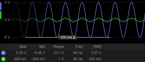
From the diagram, the green signal represents the input, and the blue represents the output. The input voltage is 0.5V peak-to-peak, and the output voltage is approximately 5V peak-to-peak, as the gain is 10. In addition, we can see that the output is in phase with the input signal since the amplifier is in a non-inverting configuration.
Input and Output Impedance
Non-inverting amplifiers have very high input impedance, often in the range of megaohms. This makes them ideal for situations where loading the input signal is undesirable, such as when the input signal comes from a sensor or a high-impedance source.
This also allows more of the signal to reach the amplifier and is important for preventing signal loss or distortion.
The output impedance is typically low, which is advantageous when driving loads that require high currents without significant signal loss or distortion. This is important for ensuring that the output signal is strong and can drive other circuits or devices.
What is the main Difference Between a Non-Inverting and Inverting Op-amp?
The key difference lies in how the input signal is applied and how the output behaves. In an inverting op-amp, the input signal is applied to the inverting terminal, and the output signal is inverted (180-degree phase shift) relative to the input. In contrast, a non-inverting amplifier produces an output that is in phase with the input signal. The input signal is also applied to the non-inverting terminal (+) of the op-amp.
Creator and Editor at AnitoCircuits.com based in Toronto
