In electronics, resistors are components designed to impede the flow of electric current, and how they’re connected in a circuit makes a big difference. There are two main setups: resistors in series and resistors in parallel.
Now why should we bother with these configurations?
If we’re designing circuits, we can leverage these configurations to achieve specific outcomes, whether it be controlling voltage, current, or achieving a desired level of resistance.
Resistors in Series Connection
Resistors in series are like a chain – they’re connected end to end, creating a single pathway for the current to flow through.
As we can see in the figure below, one resistor share only one point of connection to another resistor.

In a simple series circuit, the first resistor (R1) is connected to the positive terminal of the voltage source (Battery), and the second resistor (R2) is connected to the free end of the first resistor.
This pattern continues as each new resistor is connected to the free end of the previous one. A closed loop is completed when the free end of the last resistor is connected to the negative side of the voltage source.
Total Resistance
Now how can we get the total combined resistance?
The value of each resistor adds up. That is because the current has to overcome each resistor in its path, and the combined effect is the sum of these individual resistances.
The total resistance (R_total) can be expressed as:
\[ R_{total}=R1+R2+R3+… \]
Voltage and Current Analysis
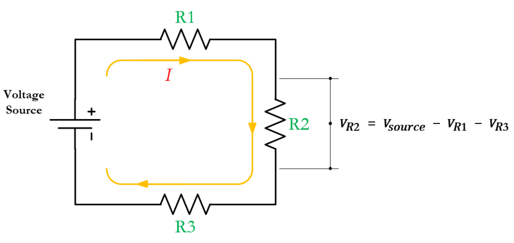
In the series circuit above, notice that the resistors configuration creates a single loop. It draws a single current from the voltage source which is also referred to as the total current.
The same current also flows through each resistor in succession. Therefore, we can say that the current through R1 is equal to the current through R2, which is also equal to the current through R3.
\[ \large I_{total} = I_1 = I_2 = I_3 \]
Meanwhile, the total voltage supplied by the battery or power source is distributed across all the resistors. That is because as current flows through each resistor, the voltage is dropped across it due to the resistance encountered.
So, this makes the voltage equation as:
\[ \large V_{total}= V_1+V_2+V_3+…\]
Additionally, it’s important to note that the total voltage is not always equally distributed across all the resistors. This scenario occurs only when all the resistors have the same value.
In a series connection, there are two ways of solving the voltage across each resistor. It’s either using the voltage divider formula or ohms law.
Ohms Law
Ohm’s Law states that the voltage (V) across a component is equal to the product of the current (I) flowing through it and its resistance (R).
\[ V = I \cdot R \]
Voltage Divider Formula
The voltage divider formula is given by:
\[ \large V = V_{total} \times \frac{R}{R_{total}} \]
Where:
- V is the voltage across the specific resistor (R).
- Vtotal is the total voltage applied to the series circuit.
- Rx is the resistance of the specific resistor for which you want to find the voltage drop.
- Rtotal is the total resistance of the series circuit.
Resistors Connected in Parallel
In a parallel circuit, resistors are connected in a branched format or let’s say linked in a manner that resembles a “ladder” or “stacks”. In this configuration, both ends of the resistors are connected to each other.

Resistors are connected in a way that provides multiple paths for the current to flow and travel independently, as shown in the figure above.
Total Resistance
Unlike resistors in series, which add up directly, resistors in parallel work together in a way that decreases the overall resistance.
The formula for calculating the total resistance in a parallel circuit is as follows:
\[ \frac {1}{R_{total}} = \frac{1}{R_1}+\frac{1}{R_2}+\frac{1}{R_3}+…\]
This formula expresses the inverse relationship between the total resistance and the sum of the reciprocals of individual resistances in parallel.
We can further simplify the expression above as:
\[ \large R_{total} = \frac{1}{\frac{1}{R_1}+\frac{1}{R_2}+\frac{1}{R_3}+…} \]
Voltage and Current Analysis
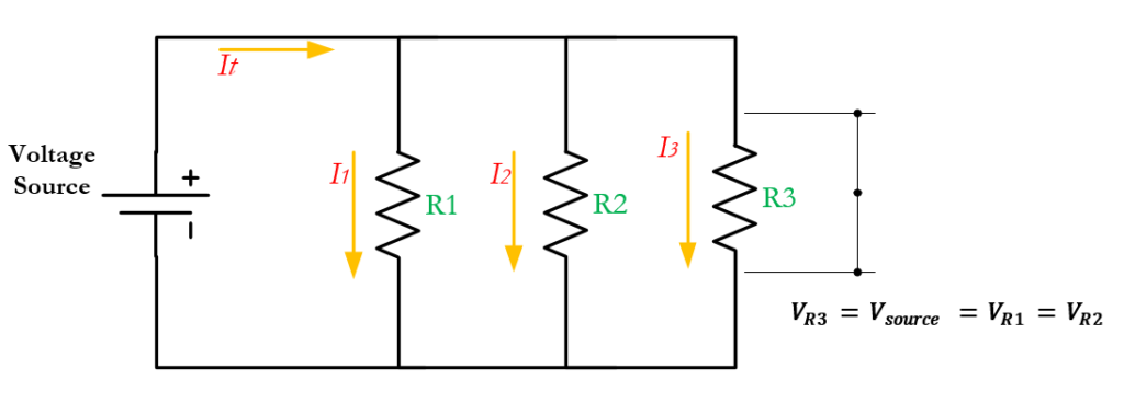
As we can see in the figure above, each resistor is directly connected across the terminals of the voltage source. This direct connection ensures that each resistor has independent voltages equal to each other.
So, from this configuration, the voltage equation can be expressed as:
\[\large V_{total} = V_1 = V_2 = V_3 \]
If the total voltage is distributed across each resistor in a series circuit, the same principle applies to current in parallel, where the total current is distributed on each branch of the circuit. This makes the current equation as:
\[\large I_{total} = I_1+I_2+I_3 +…\]
It’s also important to note that, when connected in parallel, each resistor does not necessarily have equal currents. Their individual current depend on their individual resistance values as well.
So, applying Ohm’s Law to each branch, we can calculate the current flowing through each resistor.
\[ \large I = \frac {V}{R} \]
Alternatively, the current divider formula can be applied to calculate the individual currents.
\[ \large I_{individual} = I_{total} \times \frac{R_{total}}{R_{resistor}} \]
Now that we discussed the serries and parallel connections, what if we combined them in a single circuit?
Series-Parallel Circuit
Often referred to as a series-parallel connection, this configuration adds an additional layer of complexity and versatility to a circuit design. So, the right approach to analyze this is to break the circuit down and take it one step at a time.
Let’s consider a practical and simple example of a series-parallel resistor circuit below.
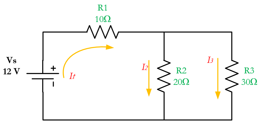
Suppose the voltage output of the battery in the circuit above is 12 V. The resistances are R1 = 10Ω, R2 = 20Ω, and R3 = 30Ω. Find the total resistance and perform current and voltage analysis for each resistor.
Solve for the Equivalent Resistance
Equivalent resistance refers to a single resistor that can replace a combination of resistors in a circuit. This is to simplify complex resistor networks into a single, equivalent resistor, and make your circuit analysis more manageable.
In this example, you can find the equivalent resistance by simplifying the circuit step by step. Some people will combine series resistors first and then address parallel resistors afterwards.
However, you can’t always do that. A common and efficient approach of simplifying complex circuits is to start combining resistors that are farthest from the voltage source. This way, you can gradually work your way towards the inner components.
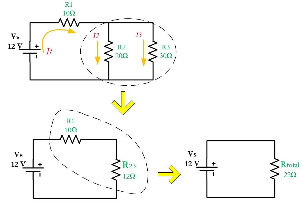
So, as we can see in the figure above, we can only combine R2 and R3 first. Let’s name their equivalent resistance as \(R_{23}\). Notice also that they are connected in parallel.
\[ \large R_{23} = \frac{1}{\frac{1}{R_2}+\frac{1}{R_3}} \]
\[\large R_{23} = \frac{1}{\frac{1}{20\Omega}+\frac{1}{30\Omega}} = 12\Omega\]
The equivalent resistance of R2 and R3 \(R_{23}\) will now be combined in series with R1. We can then proceed to calculate the total resistance of the circuit.
\[\large R_{total} = R_{23}+R_1\]
\[\large R_{total} = 12\Omega + 10\Omega = 22\Omega\]
Find the Total Current
To find the individual current and voltage drop across each resistor, we must find the total current first. In this case, it’s the easiest thing to do. Let’s analyze the equivalent circuit below.
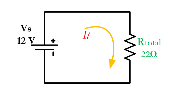
Here, we have the total voltage (Vtotal) and the total resistance (Rtotal). Using Ohms law, we can easily calculate the total current of the circuit.
\[ \large I_{total} = \frac{V_{total}}{R_{total}}\]
\[\large I_{total} = \frac {12 V}{22\Omega} = 0.55\,A\]
Note: \(I_{total} = I_1\ = I_{23}\)
Find the Voltage Drop Across Each Resistor
let’s go back to the original circuit. Notice that the total current is the same current that flows through R1 and through the combination of R2 and R3 (\(I_{tot} = I_1 = I_{23}\)). This means that using ohms law, we can find the voltage drop across R1 and \(R_{23}\).
\[ V_1 = I_1\times R_1\]
\[ V_1 = 0.55\,A \times 10\,\Omega = 5.5\, V\]
Since R2 and R3 are parallel with each other, they have the same voltages (\(V_{23} = V_2 = V_3\)). We can easily find the voltage drop across \(R_{23}\) using Ohms Law.
But to make things a little different, since \(R_{23}\) is in series with R1, we can also use the Voltage Divider Formula.
\[\large V_{23} = V_{total} \times \frac{R_{23}}{R_{total}}\]
\[\large V_{23} = 12\,V \times \frac{12\,\Omega}{22\,\Omega}=6.5\,V \]
Note: \(V_{23} = V_2 = V_3\)
Find the Individual Current
Since we have the voltage drop across each resistor, the easiest way to find find their individual currents is to use Ohm’s Law. Let’s find the current through R2.
\[ \large I_2 = \frac{V_2}{R_2}\]
\[ \large I_2 = \frac{6.5\,V}{20\,\Omega}=0.325\,A\]
Alternatively, we can also use the Current Divider Formula to find the individual currents in a parallel circuit. Let’s find the current through R3 using it.
But before doing that, it’s important to note that we should use the current that flows through the equivalent resistance of R2 and R3 (\(I_{23}\)). In this example, it’s equal to the total current.
\[ \large I_3 = I_{23}\times \frac{R_{23}}{R_3}\]
\[\large I_3 = 0.55\,A \times \frac{12\,\Omega}{30\,\Omega} = 0.22\,A\]
That’s it! We have now completed the circuit analysis. Lastly, let’s put our findings into a VIR table.
| V | I | R | |
| R1 | 5.5 V | 0.55 A | 10 Ω |
| R2 | 6.5 V | 0.325 A | 20 Ω |
| R3 | 6.5 V | 0.22 A | 30 Ω |
| Total | 12 V | 0.55 A | 22 Ω |
Creator and Editor at AnitoCircuits.com based in Toronto
