A voltage follower, also known as a buffer, is a configuration where an operational amplifier (op-amp) is set up to have a voltage gain of 1. This means the output voltage follows the input voltage, hence the term “voltage follower.”
The typical purpose of a voltage follower in most circuits is to separate or isolate different parts of a circuit so they don’t interfere with each other.
See Also:
- Learn more about the Non-inverting Operational Amplifier (Op-amp) Circuit.
Operational Amplifier Overview
An operational amplifier is a versatile, high-gain electronic voltage amplifier with differential inputs (inverting and non-inverting) and usually a single output. It can be used in various configurations, including inverting, non-inverting, and voltage follower.
A key feature of op-amps is that they can maintain the same voltage between their two input terminals when negative feedback is applied.
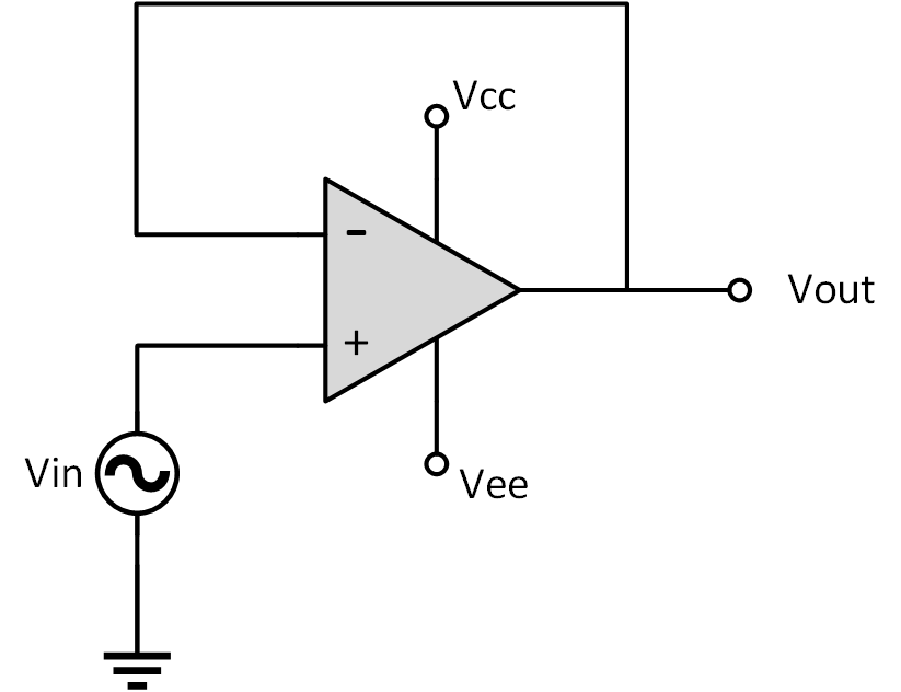
In the voltage follower configuration, the non-inverting input is connected to the signal source, and the output is directly fed back to the inverting input. This allows the output to “follow” the input signal while providing the benefit of impedance matching between different circuit stages.
Voltage Follower Configuration Circuit
The figure below shows a typical voltage follower circuit (non-inverting buffer). The output is directly connected to the inverting input (-) without any resistive network, creating a feedback loop. This setup results in a circuit with a gain of 1 (unity gain). In addition, the input voltage is applied to the non-inverting input (+), and because of the feedback, the output mirrors the input.

Input and Output Voltage Relationship
Since the gain is unity, the relationship between the input (Vin) and the output (Vout) can be described by:
\[V_{out} = V_{in}\]
\[A_v = \frac{V_{out}}{V_{in}} = 1\]
The voltage follower does not amplify the signal. The purpose of this circuit isn’t to make the signal stronger but rather to protect the signal quality as it moves from one stage of the circuit to another.
Negative Feedback Loop
Moreover, why is the output connected to the inverting terminal of the op-amp? Negative feedback plays a crucial role in the voltage follower configuration. By feeding the output directly back to the inverting input, the op-amp is forced to adjust its output to make the voltage difference between its inputs zero.
- Stability: The negative feedback ensures the output closely tracks the input voltage, providing a stable and accurate output.
- Benefits of Unity Gain Feedback Loop: The feedback loop ensures that the voltage gain remains at unity, and any disturbances in the circuit are quickly corrected by the op-amp, making the voltage follower ideal for buffering signals.
Why is the Output Not Inverted?
Even though the output of a voltage follower is connected to the inverting input of the op-amp, which might resemble an inverting configuration, the output does not become negative or inverted. This is because of the virtual short created by negative feedback. Also, please note that the feedback is connected in a way that prevents phase inversion.
So, as mentioned above, the goal of the op-amp in this setup is to keep its two inputs at the same voltage levels.
Input and Output Impedance
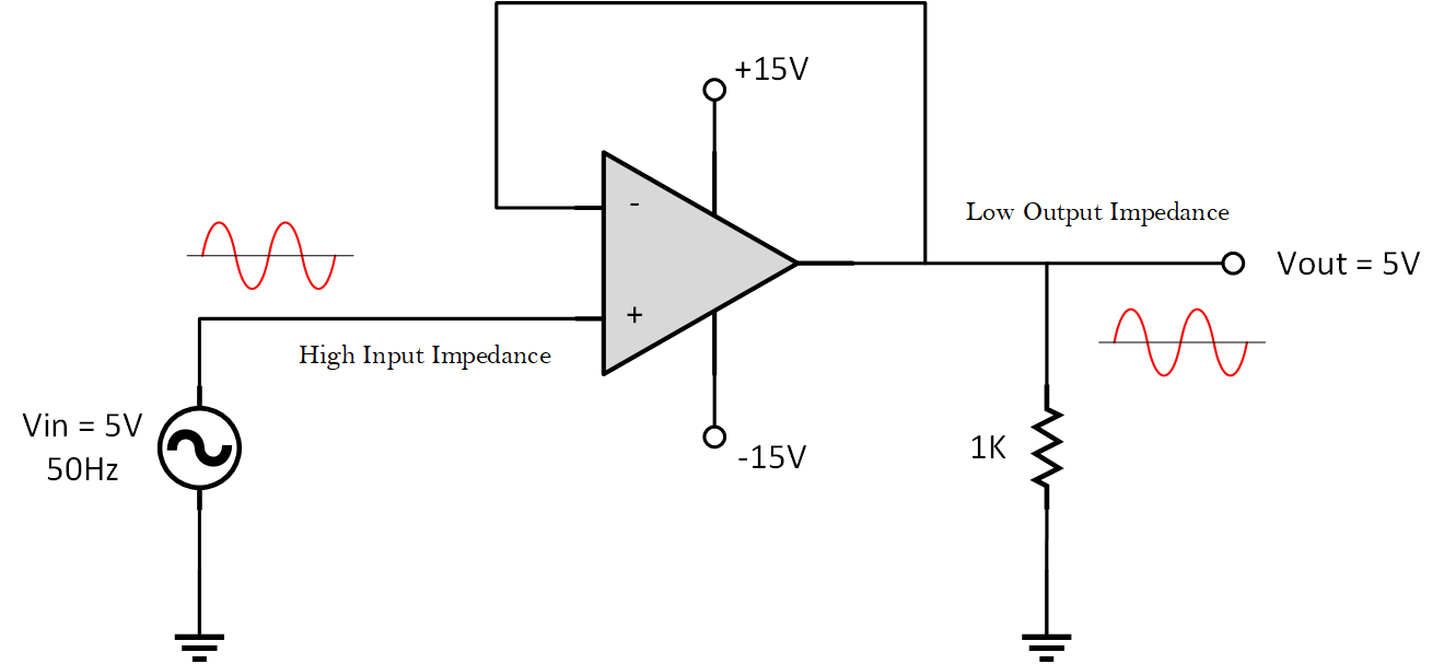
Now, it’s important to note that a voltage follower circuit is mainly designed to buffer signals by presenting a high input impedance and a low output impedance.

High Input Impedance
A voltage follower has a very high input impedance, meaning it doesn’t draw much current from the connected signal source. This characteristic is crucial when dealing with high-impedance sources, such as microphones or guitar pickups.
Remember that if these high-impedance sources are connected directly to a low-impedance input, they can become “loaded down,” leading to a reduction in signal strength and potentially distorting the sound. That is why op-amps are very useful in these situations.
Low Output Impedance
Low output impedance means that the voltage follower can drive other circuit stages without a significant voltage drop across its output, even if the next stage has a low input impedance. This quality allows the voltage follower to deliver a clean and stable signal to the next part of the circuit.
Recommended Readings:
- Explore this LM386-Based Audio Amplifier project.
Practical Applications of Voltage Followers
So, what are the common practical applications of a voltage follower? Below are some examples of how a voltage follower is used in certain circuits.
Signal Conditioning and Buffering
As we already discussed earlier, voltage followers are used in sensor circuits to ensure that the high impedance of the sensor does not affect subsequent stages.
Analog-to-Digital Converter (ADC)

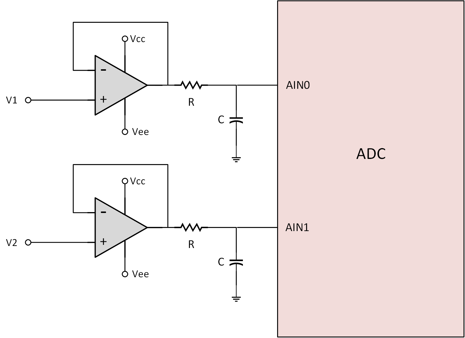
Additionally, it is often used to buffer the input of analog-to-digital converters (ADCs). In the circuit shown above, the input voltage is buffered with an op-amp before it is connected to the ADC. This buffering setup is a common method for driving ADC inputs, as it isolates the ADC from the previous stage, ensuring that the ADC receives a stable, low-impedance signal without loading the source.
This configuration also minimizes potential errors and improves the accuracy of the ADC readings by maintaining signal integrity.
Impedance Matching in Audio Circuits
In audio systems, voltage followers are used to match high-impedance sources (such as microphones) with low-impedance loads (like amplifiers) without affecting the signal quality. These circuits are often called “Pre-Amplifier Buffers” or “Line-Level Audio Buffers.”
Voltage Followers in Analog Filters

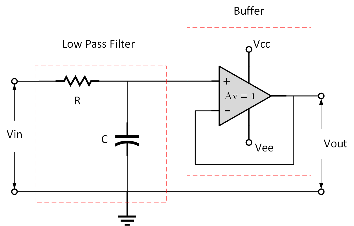
Voltage followers are often integrated into analog filter circuits, such as low-pass or high-pass filters, to isolate different stages while maintaining the integrity of the filtered signal.
Advanced Variations of Voltage Followers
While the basic voltage follower has a gain of 1, there are some advanced variations and improvements. You can explore and learn more about these variations.
Buffer with Gain
By adding resistors to the feedback loop, you can modify the buffer to provide a slight gain while maintaining its high input impedance and low output impedance properties.
Cascading Buffers
In some applications, cascading multiple voltage followers can help improve overall performance, such as reducing the total output impedance or enhancing signal integrity over long distances.
Next Steps
- Check this LED Bar Graph Meter Utilizing the LM324 Op-amp project.
- Explore Bipolar Junction Transistors (BJTs).
- Learn How to Design a 555 Astable Oscillator Circuit.
Creator and Editor at AnitoCircuits.com based in Toronto
